Help with stern tube/propshaft

sereda

Member
Joined
1 Feb 2011
Messages
88
Visit site
I would like to know how my propshaft is supported inside the stern tube and also how it is lubricated and how it prevents water from getting into the boat. I removed the prop and expected to be able to pull the shaft into the engine bay, but it did not move, tried a rubber mallet but no moving it at all. Can anyone help please.

130727-IMAG0307.jpg

130727-IMAG0308.jpg
 

vyv_cox

Well-known member
Joined
16 May 2001
Messages
25,463
Location
France, sailing Aegean Sea.
coxeng.co.uk
Your website doesn't seem to show anything like the stern tube in the OP's photos. I haven't seen one like that before.

Yes, it is unusual. The brass part inside the tube seems to have two shallow holes diametrically opposite each other. Are they to accept a spanner, suggesting that the tube is threaded internally?

I didn't know what that type of spanner is called, apparently it is a pin wrench, as used for angle grinder discs.

Another thought: are the depressions the ends of bolts, with the heads inside the boat? Similar to the photo by Roger Gaspar on my page.
 
Last edited:

sereda

Member
Joined
1 Feb 2011
Messages
88
Visit site
Thanks for the link, the 2 shallow depressions really are shallow not sure if anything would get any grip by being inserted in them. Not sure how I would get the flange off inside the engine bay either, unless it is screwed onto the shaft. There are no grub screws etc visible anywhere on the stern tube.
It is a project I am hoping to get running. It is one of only 2 or 3 boats built in 1996 ish commisioned by Honda I believe. It was powered by a little Honda GX 160 engine into a 2:1 reduction wet centrifugal clutch gearbox and possibly a flexible coupling to the prop. I bought the boat with no engine, and would love to get the shaft out before trying to get everything mated up and in the water.
 

Topcat47

Well-known member
Joined
2 Jun 2005
Messages
5,032
Location
Solent, UK
Visit site
Inside the stern tube there ought to be a bearing. The Brass collar suggests it is not a cutless bearing as the collar would impede the ingress of water needed to lubricate the bearing. Does the brass collar rotate with the shaft? Is the coupling flange connected to the shaft with a nut? it looks like it may be and were it attached to splines this would make the lack of grub screws understandable. Have you tried heat in the coupling? Honda may be able to help, but they are rather slow to reply. It took me six months to get an answer to a question regarding a CB77.
 

sereda

Member
Joined
1 Feb 2011
Messages
88
Visit site
Yes it does rotate with the shaft. No the flange is not held on with a nut. I guess I need to try and remove the flange. Stiltsons on the flange and some means of holding the prop end. I doubt Honda would be of any help, its about 17 years old.
 

rogerthebodger

Well-known member
Joined
3 Nov 2001
Messages
12,537
Visit site
It look like there is a pin through the boss of the inside coupling. If there is this will need removing before you can pull the coupling off the shaft. The pin could be a tapered pin, a parallel pin or a roll pin. If its tapered you will only be able to knock it out from one side. Pin must be removed before using your Stillsons.

The brass boss/ bearing on the outside looks like it has a key fixing it to the shaft. The brass boss could be fixed with grub screws but you will only see then once the coupling has been removed and the shaft slid out.
 

Neil_Y

Well-known member
Joined
28 Oct 2004
Messages
2,340
Location
Devon
www.h4marine.com
Probably lip seals with grease or oil, bearings could be white metal. You won't know for sure until it's dismantled. Many systems have been altered or changed over the years but the good news is that you can do straight replacement of oil or grease bearings with modern composites, these can also run quite happily on water if you choose to remove the oil and lubricate/cool with sea water.
 

sereda

Member
Joined
1 Feb 2011
Messages
88
Visit site
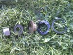
Well better late than never I got the shaft out. The brass thing in the prop end of the shaft held a lip seal, behind that was a circlip which is held in the stern tube then a standard 17mm x 40mm 5203 2RS bearing, then a small lip on the stern tube to prevent the bearing going any further up the tube.
Now at the engine side of the shaft the shaft is 20mm diameter and there is almost nothing left of the bearing. There is a small lip about 2 inches down the stern tube to prevent the bearing going down the tube. No body makes a 20mm x 40mm bearing, except for thrust bearings, would it have been a thrust bearing? If so I dont understand how it stays in place and stays together as they come in three parts.
The engine is a little 5.5 HP, driving the shaft through a 2:1 reduction gearbox with centrifugal clutch and obviously only ever rotating in one direction, no reverse.
 

sereda

Member
Joined
1 Feb 2011
Messages
88
Visit site
This is what I have, I do not understand where the thrust is applied to the hull - through the engine/gearbox or through the shaft and bearings. Would the lip seal prevent water getting up the stern tube and what sort of bearing should there be at the inboard end as it is a 20mm shaft and 40mm I/D stern tube.

130803-IMG_20130803_184300.jpg

img013.jpg
 
Last edited:
Top