DIY Chain Counter - Again!!!

vas

Well-known member
Joined
21 Jun 2011
Messages
8,082
Location
Volos-Athens
Visit site
Spoiler Alert
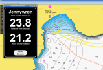
Mobile Phone ScreenShot

View attachment 144774
I see that and raise you ?

grafana_overview.jpg

on a serious note, this bleeding chain counter is one of the worst bits of code I've gone through.
Tested all winter last year with the boat in port and engines off, worked a treat.
Throughout the season with engines obviously running, some electromagnetic noise was picked up somewhere and values are slow in dropping (or quick in retrieving, still to work that out!)

and reading you latest post, that's exactly how I'm dealing with up and down, imho the only way to do it! and I'm keeping current chain out in an sdcard so even if system reboots it will read the value from the sd and start where it should.
I'm lucky that garmin GMI10/20 are capable of presenting N0183 sentences of chain out (from an old AutoAnchor black box) so I'm viewing that on the f/b as the chain is dropped/retrieved.


V.

PS. grafana, presenting N2K data that go to my office server via signalK running on a raspberry onboard.
 
Last edited:

Hurricane

Well-known member
Joined
11 Nov 2005
Messages
9,587
Location
Sant Carles de la Ràpita
Visit site
I see that and raise you ?

View attachment 144819

on a serious note, this bleeding chain counter is one of the worst bits of code I've gone through.
Tested all winter last year with the boat in port and engines off, worked a treat.
Throughout the season with engines obviously running, some electromagnetic noise was picked up somewhere and values are slow in dropping (or quick in retrieving, still to work that out!)

and reading you latest post, that's exactly how I'm dealing with up and down, imho the only way to do it! and I'm keeping current chain out in an sdcard so even if system reboots it will read the value from the sd and start where it should.
I'm lucky that garmin GMI10/20 are capable of presenting N0183 sentences of chain out (from an old AutoAnchor black box) so I'm viewing that on the f/b as the chain is dropped/retrieved.


V.

PS. grafana, presenting N2K data that go to my office server via signalK running on a raspberry onboard.
Thanks Vas

Even though this is the third time (I think) that I've written my own anchor counter, I've learned new stuff this time.
I will probably say this again but one big mistake/bug this time was assuming that the anchor stopped immediately.
In fact, if you watch it, you will see that it takes about a second to stop winding.
And in that time, it can play havoc with your logic.
Anyway, as I say, more to follow.
Thanks for your post.
 

MapisM

Well-known member
Joined
11 Mar 2002
Messages
20,484
Visit site
I never progressed beyond red paint every 10 meters and counting 1, 2, 3 etc as the chain deploys.
I sympathize with your approach, but your memory is obviously better than mine.
I used the coloured Osculati inserts every 10 meters because, on top of not needing any repainting, with your system I would forget how much chain I deployed a minute after I did... :giggle:
And by leaving the coloured marks in sight (either still onboard or just under the roller), it's easier to re-check and possibly let out some more chain whenever the wind picks up.
 

Portofino

Well-known member
Joined
10 Apr 2011
Messages
12,293
Location
Boat- Western Med
Visit site
Another less techy approach is the mk1 eyeball .
Just look in the locker how much is left , 1/2 , 1/3 rd etc . It’s what my Admiral does ……..seems to work .

We were in 25 M so we dumped 2/3 rds of the 70 , so I was told for a days anchorage.Light breeze .No swinging .
Evening we departed to a marina .

Itama @ anchor

The large blue yacht off the port bow 1/4 + the charter day boat ( out of nearby Portofino) arrived after us and departed before .
 

Hurricane

Well-known member
Joined
11 Nov 2005
Messages
9,587
Location
Sant Carles de la Ràpita
Visit site
This next post is about building the prototype and getting something to work.
I hope this isn't too detailed/boring but I am trying to be as complete as possible.
Some people might find these techniques helpful for other projects as well as this chain counter project.

At this stage I have to say that I haven't had any formal training in electronics or software.
I would really have liked to have done some kind of electronics at school but it wasn't offered at any stage of my education.
Everything that I have done in this field is "self taught.
During the 80s and 90s, I ran a successful computer business but I wasn't the "brains" behind our team.
However, I was very enthusiastic in the early days of micro computers.
In those days, we worked with the Zilog Z80 - my first computer being a home built Nascom.
Eventually expanding it to a full CP/M computer.
During those days, I learned a lot about programming - in assembler and (my favorite) the C language.

Thats the end of my "potted history" - back to the chain counter.

The next step was to "dig out" an old Raspberry Pi, load a fresh copy of Linux onto a microSD card and boot it.
I chose the Lite version of Raspberry Pi OS (used to be called Raspbian).
The Lite version doesn't have a GUI desktop - only a simple command line shell.
I chose that because I don't want any unnecessary software slowing the system down.
In order to work with the Raspberry Pi, I initially connected a monitor and keyboard.
But once running, I connected the Raspberry Pi to my home LAN using its Ethernet interface.
And then ran SSH on my Linux desktop computer to connect to it.
If I had been using Windows (yuk) I could have used PUTTY which allows Windows computers to connect to remote devices using SSH protocol.

This is a typical screenshot of my desktop computer whilst connected to the Raspberry Pi using SSH.

ChainCounterTerminal.resized.png

The beauty of this approach is that my desktop computer can then "cut/paste" to/from the Raspberry Pi.
Using this SSH approach/connection, I installed node.js and the software libraries that I needed.
Specifically, I installed that onoff library that handles the interrupts so well.
I then wrote a simple test application
I tend to write the code on my desktop computer and then cut/paste it onto the Raspberry Pi.
Then, if anything went wrong, I still had the code that I had written up to that point.
I won't actually explain my software code in this post but if anyone is interested, I am happy to publish it.
I've never used GitHub so maybe this is an opportunity to "open source" this project and make it available for anyone.

I then wired up a "breadboard" to connect two switches and a few resistors to the Raspberry Pi digital header.
These switches were to mimic the two inputs to the chain counter.
I don't have any photos of that setup but I did make a short video at this stage of the project.
In the following video the two switches connect to the breadboard and the breadboard is wired to the Raspberry Pi
In the video, the small switch (which is mostly in my hand) is a "momentary push button" which mimics the windlass capstan reed switch.
The other switch is a simple on/off switch which determines if the windlass "up button" is pressed or not.

ChainCounter1
EDIT - Sorry, I don't seem to be able to embed the video into the forum as usual - just click the link to view the video

Note that the Raspberry Pi's web server is running and showing the display.
In this video, I used an Android phone but the same display is available on any device/computer by running a browser.
Also note that every time I press the "momentary push button" (windlass reed switch) the Raspberry Pi increments the counter on the mobile phone by the amount of the chain that is wrapped around the gypsy.
During the video, I switched the on/off switch to mimic the recovery of the anchor.

Using this little test rig, I was able to ensure that the Raspberry Pi didn't miss a "momentary push button" press and that it didn't inject any false inputs.

At this stage, I will break and start again on another post.
The next post will explain how I connected this fragile little device to the electrically noisy environment when big electric motors are switched on and off with relays etc.

I hope you are finding this interesting.
 
Last edited:

Meagain

Active member
Joined
17 Jul 2019
Messages
110
Visit site
many thanks for sharing this thread, it’s great to read constructive postings like this and really like what you are trying to achieve, must admit programming language a bit over my head at the moment but give it time ! May be a silly point a the moment but why is the count in Your test not equal ie 0.4? As each revolution should let out the same length of chain.
 

benjenbav

Well-known member
Joined
12 Aug 2004
Messages
15,354
Visit site
I sympathize with your approach, but your memory is obviously better than mine.
I used the coloured Osculati inserts every 10 meters because, on top of not needing any repainting, with your system I would forget how much chain I deployed a minute after I did... :giggle:
And by leaving the coloured marks in sight (either still onboard or just under the roller), it's easier to re-check and possibly let out some more chain whenever the wind picks up.
I’m pretty sure I wouldn’t ever have remembered how much chain was out a minute later either. I was much more of a ‘set it and forget it’ mindset…

Except that the anchor alarm would always be set and transits checked by eye and also - being in a more tide-dominated environment than the Med - I always wanted to monitor what was going on as the tide turned and to re-set if necessary. ?‍♂️
 

Hurricane

Well-known member
Joined
11 Nov 2005
Messages
9,587
Location
Sant Carles de la Ràpita
Visit site
many thanks for sharing this thread, it’s great to read constructive postings like this and really like what you are trying to achieve, must admit programming language a bit over my head at the moment but give it time ! May be a silly point a the moment but why is the count in Your test not equal ie 0.4? As each revolution should let out the same length of chain.
Thanks for the reply.
Interesting that you noticed the step change at each revolution.
The answer is simple.
In my software, I count and store the number of times that the reed switch has been triggered.
In the final design this will be the number of revolutions that the gypsy has made since the anchor left the deck.
The web software then converts the number of revolutions to the actual amount of chain deployed.
My gypsy's circumference is 360mm so I multiply 360 by the number of revolutions and divide by 1000 to get the actual amount of metres of chain deployed.
But I thought it a bit silly having more than one decimal place so it "rounds up" just before updating the web interface.
That is why the increments are sometimes 0.4m and other times 0.3m.
All intended.
I hope that answers your question.
 

Hurricane

Well-known member
Joined
11 Nov 2005
Messages
9,587
Location
Sant Carles de la Ràpita
Visit site
This next episode explains how I connected the Raspberry Pi into the boat.

Over the years, I have installed a number of voltage stabilisers.
These devices ensure that my fragile electronics don't get damaged by electric spikes whenever some of the high power systems are operated.
Things like thrusters and winches etc can cause voltage fluctuations that will damage fragile electronics.
I have sensitive kit like LEDs and docking cameras and anchor cameras etc.
Here is a link to the kind of thing that I use throughout the boat:-
http://www.amperor.com/products/air_auto_brick/pdf/ADP90DC-12_Spec_Rev01.pdf

Our Princess has its windlass relay installed in a dry space behind a panel in the forward cabin.
A few years ago, I installed a voltage stabiliser in that space to power our anchor camera.
That stabiliser also drops the voltage from 24v to 12v.
So I used that existing stabiliser to power the Raspberry Pi .
And then used a cheap DC to DC Buck converter to drop the 12v to 5v suitable for the Raspberry Pi's power input.
Something like this:-
https://www.amazon.co.uk/Converter-Regulator-Waterproof-Inverter-Smartphone/dp/B07H7X37T6/ref=sr_1_5?crid=NDPUUBWJKXJ1&keywords=12v+to+micro+usb&qid=1666602030&qu=eyJxc2MiOiIzLjAzIiwicXNhIjoiMi40OSIsInFzcCI6IjEuODgifQ==&sprefix=12v+to+micro+usb,aps,232&sr=8-5

So, that combination will safely power the Raspberry Pi itself.
But what about the actual digital connections between the windlass reed switch and the windlass "up button".
You could use a relay but I was worried about introducing extra delays and extra wiring.
So I use Opto Isolators (sometimes referred to as Opto Couplers).
These little single chip devices use an LED and light sensitive transistor internally built into a chip.
Here is a photo of one that I "breadboarded" to test my design.

image003.resized.jpg

To use these devices, you need to need to add some resistors to limit the current flow.
Here is a circuit similar to the one that I used.

image001.resized.jpg

As you can see, the nasty 24v world (on the left) is completely isolated from the fragile 3.3v of the Raspberry Pi's inputs (on the right).

The next step was to test this using the Raspberry Pi and the software written earlier.
So, I breadboarded both of the Raspberry Pis inputs.
Like this:-

image002.resized.jpg

Obviously, a breadboard is only for testing so I needed something more robust.
Raspberry Pis are often extended using a Raspberry Pi "Hat".
There are lots of "Hats" available for Raspberry Pis but I couldnt find a suitable Opto Isolator Hat.
So I built my own DIY one using one of these:-

20220701_154157.resized.resized.jpg

I, simply soldered up the components in the same way as the breadboard prototype.

And this video link shows the result.

ChainCounter2

Note that in the above video clip, I used a PC browser to display the chain counter output.

Finally, before I finish this episode, here is a circuit diagram of the final DIY Raspberry Pi Hat

Opto Diag.resized.jpg

Next episode will discuss the installation and debugging that I had to do get it all working reliably.
I don't know but maybe some people will be finding this interesting.
 

TonyR123

Active member
Joined
20 Feb 2016
Messages
499
Location
Puerto Portals
Visit site
+1 for finding this interesting. My degree was in Electronics, but worked all my life in software development. Have messed around with the Pi before but nothing of interest. My current chain counter needs resetting fairly often (say twice a year) due to chain slippage I guess.
 

Hurricane

Well-known member
Joined
11 Nov 2005
Messages
9,587
Location
Sant Carles de la Ràpita
Visit site
+1 for finding this interesting. My degree was in Electronics, but worked all my life in software development. Have messed around with the Pi before but nothing of interest. My current chain counter needs resetting fairly often (say twice a year) due to chain slippage I guess.
I don't think the chain slips - even if the windlass clutch slips.
With your background, maybe you should do something similar to my chain counter.
That said, I had a problem with the chain deployed didn't reset to zero when recovered.
But I will explain that issue in the next installment.
 

TonyR123

Active member
Joined
20 Feb 2016
Messages
499
Location
Puerto Portals
Visit site
I don't think the chain slips - even if the windlass clutch slips.
With your background, maybe you should do something similar to my chain counter.
That said, I had a problem with the chain deployed didn't reset to zero when recovered.
But I will explain that issue in the next installment.

Probably right - as for doing something the same will see if I have the same issue with the new boat next year! TBH I am struggling for time. Am doing some software development (again) and also just got a sailing boat for the UK.
 

Hurricane

Well-known member
Joined
11 Nov 2005
Messages
9,587
Location
Sant Carles de la Ràpita
Visit site
Getting to the end now.
This episode will discuss the installation and debugging that I had to do get it all working reliably.
And some photos of the final result.

As said above, my windlass relay is installed behind a panel in the forward cabin where I also installed a voltage stabiliser a few years ago.
That stabiliser supplies power to my anchor camera.
Close by, an Ethernet cable connects the anchor camera to the ships LAN.
So, as part of this chain counter installation, I also fitted a low cost Ethernet switch.
This allowed me to connect the Raspberry Pi into the ships LAN.
I built the whole assembly into a plastic enclosure.

ed010667-7125-43df-b8a9-aa2215db1fbf.resized.rotated.resized.jpeg

Connecting into my LAN makes this installation a bit specific.
I set the Raspberry Pi up to have a static address on my LAN so that I always know the address to navigate a browser.
If anyone else wanted to use this project, it should be easy to use the Raspberry Pi's WiFi to connect either into a router or to set up a specific single connection.
And then access it using a mobile phone.
For example, you could connect an iPhone to the Raspberry Pi using WiFi and then run Safari to read the amount of chain deployed.

A small twist in the design.
You may have noticed a button on the screen "Reset Counter".
From time to time, it may be necessary to reset the counter to zero when the anchor is fully stowed.
So that button will reset the counter which is stored on the Raspberry Pis microSD card.
The system does this by loading another HTML page.
Actually, the browser navigates to the Raspberry Pi's IP_Address/reset to load that page.

As an alternative I also built a third HTML page which only displays the counter (no other text).
I did this to keep my ships computer screen less cluttered when other applications are running.

So with all this installed, we set off to Ibiza in late September for a short cruise.
When we anchored, everything seemed to be OK but when the anchor was recovered, it didn't set the counter back to zero.
I had a couple of attempts to check it but it was obvious that something was very wrong with the design.

But here are a couple of photos of one of JWs flybridge screens whilst at anchor in Ibiza.

On the first photo, the background application is OpenCPN.
The other application that looks like an instrument is my "Mikemarine" Logger which "talks" during passages but thats another story!!
The black window in this photo is displaying the alternative view of the anchor counter - displaying the total amount of chain deployed.

20220916_151105 (copy).resized.jpg

This second photo also includes the view from Ancam - the Anchor Camera.
The screen is a bit cluttered but each window can be enabled or disabled quickly.

20220916_151436e.resized.jpg

It was all a bit of a shame - because it didn't work!!

So when I got back to Sant Carles, I spent some time writing diagnostic routines to see where it was going wrong.
After a while, I discovered the problem.
If you remember the logic - back in an early post went something like this.
Consider the counter to increment unless the "up button" is pressed in which case the counter should be decremented.
The software logic went like this:-
In my software interrupt routine for the windlass reed switch, every time that it was "triggered", I checked the "up button" and then incremented or decremented accordingly.
But the Raspberry Pi system was responding so quickly that it wasn't giving time for the windlass to slow down.
It can take up to a second for the capstan to stop rotating during which time, it might trigger another count - and, of course, the "up button" might have been released at that time causing an incorrect increment in the counter.
So I modified the software to include a 3 second "sticky" timer (my name for it) to ensure that the counter was correct under all circumstances.

And guess what "It works"

Finally, after getting it working, I showed it to djefabs from this forum.
He does a lot of single handed boating so he usually operates his anchor from his helm positions.
He has markers on his chain to show when the anchor has just broken the surface of the water.
We are also often asked how much chain we have deployed and it makes sense to know how much chain is actually deployed in the water.
Anyway, djefabs suggested that I should change my software to include a calculation for the amount of chain actually in the water.
This will also show when the anchor breaks the surface of the water whilst it is being recovered.

So, I altered the software to include that calculation and this is the final result.

ChainCounter2.resized.png

and on a mobile phone it looks like this

Screenshot_20221021-174919_Firefox.resized.jpg

I hope you have found this interesting.
I have certainly enjoyed building it and working again with the Raspberry Pi.
If anyone wants to do something similar, just let me know.
As you know Raspberry Pis are very cheap and the rest of the bits are only a few quid - sometimes even only a few pence.
 

Andrew_Trayfoot

Active member
Joined
11 Oct 2007
Messages
671
Visit site
This next post is about building the prototype and getting something to work.
I hope this isn't too detailed/boring but I am trying to be as complete as possible.
Some people might find these techniques helpful for other projects as well as this chain counter project.

At this stage I have to say that I haven't had any formal training in electronics or software.
I would really have liked to have done some kind of electronics at school but it wasn't offered at any stage of my education.
Everything that I have done in this field is "self taught.
During the 80s and 90s, I ran a successful computer business but I wasn't the "brains" behind our team.
However, I was very enthusiastic in the early days of micro computers.
In those days, we worked with the Zilog Z80 - my first computer being a home built Nascom.
Eventually expanding it to a full CP/M computer.
During those days, I learned a lot about programming - in assembler and (my favorite) the C language.

Thats the end of my "potted history" - back to the chain counter.

The next step was to "dig out" an old Raspberry Pi, load a fresh copy of Linux onto a microSD card and boot it.
I chose the Lite version of Raspberry Pi OS (used to be called Raspbian).
The Lite version doesn't have a GUI desktop - only a simple command line shell.
I chose that because I don't want any unnecessary software slowing the system down.
In order to work with the Raspberry Pi, I initially connected a monitor and keyboard.
But once running, I connected the Raspberry Pi to my home LAN using its Ethernet interface.
And then ran SSH on my Linux desktop computer to connect to it.
If I had been using Windows (yuk) I could have used PUTTY which allows Windows computers to connect to remote devices using SSH protocol.

This is a typical screenshot of my desktop computer whilst connected to the Raspberry Pi using SSH.

View attachment 144846

The beauty of this approach is that my desktop computer can then "cut/paste" to/from the Raspberry Pi.
Using this SSH approach/connection, I installed node.js and the software libraries that I needed.
Specifically, I installed that onoff library that handles the interrupts so well.
I then wrote a simple test application
I tend to write the code on my desktop computer and then cut/paste it onto the Raspberry Pi.
Then, if anything went wrong, I still had the code that I had written up to that point.
I won't actually explain my software code in this post but if anyone is interested, I am happy to publish it.
I've never used GitHub so maybe this is an opportunity to "open source" this project and make it available for anyone.

I then wired up a "breadboard" to connect two switches and a few resistors to the Raspberry Pi digital header.
These switches were to mimic the two inputs to the chain counter.
I don't have any photos of that setup but I did make a short video at this stage of the project.
In the following video the two switches connect to the breadboard and the breadboard is wired to the Raspberry Pi
In the video, the small switch (which is mostly in my hand) is a "momentary push button" which mimics the windlass capstan reed switch.
The other switch is a simple on/off switch which determines if the windlass "up button" is pressed or not.

ChainCounter1
EDIT - Sorry, I don't seem to be able to embed the video into the forum as usual - just click the link to view the video

Note that the Raspberry Pi's web server is running and showing the display.
In this video, I used an Android phone but the same display is available on any device/computer by running a browser.
Also note that every time I press the "momentary push button" (windlass reed switch) the Raspberry Pi increments the counter on the mobile phone by the amount of the chain that is wrapped around the gypsy.
During the video, I switched the on/off switch to mimic the recovery of the anchor.

Using this little test rig, I was able to ensure that the Raspberry Pi didn't miss a "momentary push button" press and that it didn't inject any false inputs.

At this stage, I will break and start again on another post.
The next post will explain how I connected this fragile little device to the electrically noisy environment when big electric motors are switched on and off with relays etc.

I hope you are finding this interesting.
Hi,
Can you publish your code for this please.
Am interested in doing something similar.

Also do you have the part Number for the Opto Isolator you used please.

Thanks,

Andrew
 
Last edited:

Hurricane

Well-known member
Joined
11 Nov 2005
Messages
9,587
Location
Sant Carles de la Ràpita
Visit site
Hi,
Can you publish your code for this please.
Am interested in doing something similar.

Also do you have the part Number for the Opto Isolator you used please.

Thanks,

Andrew
I'm currently on a ferry crossing Biscay on the way home from the boat. I will write a full reply when I get home. I haven't used Github before so this seems a good place to start. That way, I can publish it as a complete project including code.
A couple of weeks ago, we were in the boatyard and unloaded all 150m of our anchor chain. So that was a good opportunity to check the accuracy of the chain counter. And, yes, it works well over long chain with lots of stopping and starting.
Very pleased with the result. Finally I have made a reliable DIY chain counter.
 

st599

Well-known member
Joined
9 Jan 2006
Messages
7,529
Visit site
One possible update may be to look at MQTT for publishing updates to the network. There are lots of tools available for monitoring, manipulating and displaying such data.

Could probably send a few sentences like:
/boat/hardware/windlass/up_switch off
/boat/hardware/windlass/down_switch on
/boat/hardware/windlass/current_chain_deployed_m 54
 

Keith-i

Well-known member
Joined
4 Jul 2012
Messages
1,440
Location
Jersey
Visit site
I don’t know whether this is feasible or not but is there not some kind of RFID chip you could fix to the chain at say 5m intervals and then use a reader to log the RFID ID each time one passes and therefore know what multiple of 5m length has been deployed. Each chip would have a unique ID so no counting in the normal sense would be required.
 
Top