Alex_Blackwood
Well-Known Member
Why not a suitable variable resistor? I suspect that the scooter may have been a permanent magnet motor, with straight reversal of +/- for direction. Don't quote me on that. A lot of lack of knowledge on this one. Where is Paul R who probably knows all about the BT set up!It all seems very complicated especially as you do not know the arrangement that was used in the scooter motor for this controller. Even if you got it going it may well be destroyed by back EMF. I would suggest perhaps a mediocre solution might be to fit a resistor in the negative or positive supply to reduce the speed and then add a relay across the resistor to give choice of full or partial power. Resistor could be in the form of stainless steel plate where distance between bolt hole connections and width and thickness of plate determine resistance so speed on low. I would start with 18g ss 10cm between bolt holes and 30mm wide. See how that looks for resistance. ol'will
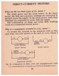
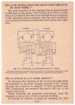
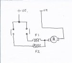
The more that I have looked at BT and windlass set ups, the more convinced I am that the motors have two field windings, probably in series with the armature, wound to give direction.
Last edited:


