Dufton
Active Member
You mean the fact that I managed to re-post successfully!? Haha - thank you.Very impressive!
You mean the fact that I managed to re-post successfully!? Haha - thank you.Very impressive!
The fact that you redesigned it before you built it ?You mean the fact that I managed to re-post successfully!? Haha - thank you.


I really like how you added the rounded edges....I bet most people looking at the finished product will think it’s molded fiberglassTopsides Alterations - Part 2
2. Secondly, I was particularly keen wherever possible to avoid any sharp edges at the point of intersection of any two plates, as I was aware that this would be the most vulnerable position for wear, and where paint would be at its thinnest - and hence also the areas most vulnerable to rust. So, wherever feasible, I ‘welded in’ curves by using a suitable cut-down lengthways section of round tube to give a rounded corner - for example, around the intersection of the front window and side window plates as seen in the picture. This involves considerable extra work, not just to cut out a ‘quarter’ section of pipe along its length, but also to then appropriately and accurately trim down both plates to be joined, and then extra work to fully weld in the section on both sides.
View attachment 147448
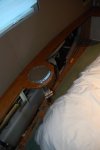
3. Side deck steps/engine room air intake. As much of the engine room is below the waterline, I was anxious to find a way of adding sufficient unobtrusive engine room ventilation higher up on the craft. The original design gives a difference in levels of the aft deck to the side decks of about 500mm and hence demanded that a step between the two levels be fabricated either side. My plan was to incorporate an engine room vent “tube” within each of the fabricated step areas - which involved adding a short extension forward of the aft deck on either side up to the edge of the rearmost windows - thus creating a void below - and then cutting down through the side deck directly into the engine room. I then attached a stainless grille to the face of the top step.
View attachment 147457
4. Another area of major alteration to the BR plans I made was to add a horizontal metal capping and downwards return to the side decks and flybridge bulwarks as a replacement to the BR design of simply welding on a 1” tube to the top edge of the outer topmost side plates. This allowed a far neater and substantial ‘finished look’ and a provided a strong suitable raised and unobtrusive mounting point for railings and cleats. My plan included the eventual fabrication of a faux teak capping fixed over the top of the side bulwarks to give protection in this particularly vulnerable area.
View attachment 147449
View attachment 147458
5. The final alterations I made to the topsides was to fabricate a shaped raised platform in the forward bow deck area in order to more neatly accommodate the electric windlass, anchor stowage and forward cleats and fairleads.
View attachment 147453View attachment 147454
View attachment 147455
Sterngear Alterations
In addition to the alterations I made on the topsides, when fitting the keel plates, I also extended them downwards and backwards to accommodate a larger and more efficient rudder. This correspondingly meant the rudder tube was positioned in a much more convenient aftward position within the aft cabin (right at the back of the cabin and not under the bed), allowing better use of internal space whilst giving easier full access for emergency tiller operation. It also meant the tube assembly could be designed so that its top was positioned safely well above the waterlne.
View attachment 147450
View attachment 147451
View attachment 147452
Thank you. I am enjoying the exercise of recalling and recording it all!That is an absolute fantastic build and the attention to detail is inspiring.
Thanks for posting.
Yes a few people have queried it!I really like how you added the rounded edges....I bet most people looking at the finished product will think it’s molded fiberglass

So is the boat now double skinned ?Web frame internal stiffeners
As part of the design changes BR had made to the kit just prior to my purchase, the vessel’s potential RCD rating was upgraded to Category A. A substantial part of this upgrade involved an update to each of the web frames by specifying the retrofit of a 70mm x 4mm steel flat shaped to fit the internal profile of the frame and welded at right angles to it. This effectively transformed the area around each frame to have the structural qualities of an ‘I’ beam rather than a simple “T” beam. This turned out to be quite a time consuming process as it proved difficult to get a snug fit and accurate bends as they were quite complex shapes. It also made the internal painting process much more trickier and created areas quite difficult to access. One advantage however was that the flats later provided a very useful attachment point either side of each web frame in order to fit the wooden battens required for panelling out.
View attachment 148039
Welding
Once all the alterations had been made, and the whole vessel had been tack-welded together it was time to do the final welds. The supplied welding specification plan was easy to follow and, depending on the location, called for one of five different patterns of weld ranging from full continuous welds both internally and externally on the main exterior plates to intermittent 50mm runs with 100mm gaps on alternate sides for areas such as attaching the stringers to the side plates and the internal stiffeners on the web frames. All welds were carried out using standard engineering practice, and I was particularly careful to alternate short runs on alternate sides to prevent uneven pull and distortion. Most of the welds were done with a MIG welder but some of the trickier hard to access areas were done with an inverter stick welder. All in all, the welding did prove to be a marathon task taking up most of the summer of the second year of the build - there is a lot of metal!! If I recall correctly, BR estimates there is about 400 hours of actual welding and I don’t think this will be far wrong! After each weld, I cleaned off the weld itself, any spatter and any burnt-off paint areas on both sides, and applied further sigma primer.
Weld dressing
All welds above the waterline were fully dressed and rounded off using a small angle grinder and a specialist die grinder with shaped carbide burr heads. This represented many hours of further work particularly for intricate areas such as around the swim platform stairs where there were some very awkward hard to reach corners etc. Below the waterline, any sharp edges of welds were rounded off but were otherwise left largely intact.
It is not double skinned in a proper structural sense. It is steel on the outside, then an air gap (with insulation layers) and then an internal plywood skin attached to the added flats on the web frames. The various internal finishes are then attached to the plywood.So is the boat now double skinned ?
 not much can go on in village that small without everyone knowing.
Thank you for that!Amazing build and a beautiful boat, It must have caused a lot of discussion in Dufton
Thank you for that!
Although there were the obligatory naysayers and ignorant doomsters of course, it is fair to say that most people in the village were very positive and supportive about the build. I did try to keep noise to sensible hours and the vessel was largely hidden away behind trees and shrubbery so it didn’t really become a nuisance or eyesore and many visitors to the village didn’t even notice it there. I think there was some natural scepticism about whether a village at the foot of the Pennine hills miles from any water was the wisest choice of build sites; and as the years went by I think many thought it would never be finished and launched - especially as progress, particularly after the initial stages, was often unseen. Rather amusingly, I did hear someone once say that the boat had been there that long it was now on the OS maps of the area!!
All in all though, I do owe a lot to the village so thought it only fitting to name her after it.
")
Thank you for your comments.You mentioned doing 50mm welds then 100mm gaps. Is there any reason for that? Why is the whole lot not fully welded on every join?
Genuine question ?
Awesome thread and thank you for taking the time to write up your journey!