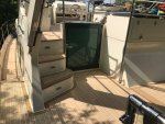
My Steel Boat Build - "Dufton" (Bruce Roberts Euro 1200 Aft Cab)

Dufton

Member
Joined
26 Aug 2018
Messages
46
Visit site
The Bottom Plates

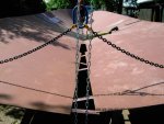
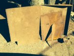
The four bottom plates are the biggest of all the plates and weigh around 500kg each. They are each up to 6m x 2m in size and made from 5mm steel plate whereas the rest of the plates of the boat are 4mm.

PICT0740.jpeg

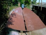
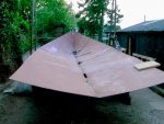
The first job was to place these four plates on the cradle allowing them to form the shape provided at each of the three resting stations formed from the erected castles. Each bottom plate makes up a corner piece of the bottom hull with a 1mm gap between it and its two neighbours - thus forming a 1mm cross gap in the middle of the hull to allow full penetration welds at these critical points. Sounds easy enough!? Hm!

It is true to say this is the only point in the build that I briefly doubted myself and wondered whether I had in fact embarked on something beyond my experience and capabilities!

The challenges I came across were numerous:
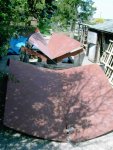
  • Each bottom plate weighs about 500kg so is impossible to move by hand
  • Initially I really struggled to fully cope with the handling characteristics of plate. I was, up until then, used to handling wood which if moved one end, was sure to provide at the opposite unsupported end an equal and opposite direction of movement!
  • There seemed to me to be a fundamental design flaw in the cradle in that there is only three supporting stations. This means that the two front plates were relatively better supported as they rested on two stations but the aft (heavier) two rested on just the one station. The result of this was that when first placed in position, the plates just flopped over either side of their respective supports - a particularly pronounced problem for the rear plates.
  • The cradle stations form a ‘V’ shape to help form the bottom shape of the hull at that respective point. Particularly at the front, the ‘V’ is quite pronounced. The problem comes as each “V’ support is left open at the bottom with a big gap in order to allow access for welding the central longitudinal seam. Of course, that then means each plate when placed in the cradle, slips down towards the centre and is in doing so becomes impossible to butt against its neighbour.
  • Even when the plates were eventually prevented from slipping out of position in relation to each other (as detailed below) it just seemed as if they had been cut to the wrong shape and would be impossible to make them come together.
2003-06-30 13.19.49.jpeg
PICT0755.jpeg

After a lot of thought, trial and error and perseverance, I developed the following techniques to manoeuvre the plates to get the perfect positioning and fit. These may well be recognised as standard fitter practices but unfortunately I had to find them out the hard way!
  • I welded temporary lugs onto the surface of plates to allow the block and tackles suspended from the gantry, and other places, to be attached at different places, to give lift or pull as necessary. Together with jacks and wedges against the floor walls and other fixed objects it was possible to help position the plates. Thus, the limited working space for the build wedged between my workshop and elevated garden wall and shrubbery actually proved very advantageous as there proved plenty of fixed objects to lever against.
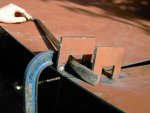
  • I welded staggered temporary notched lugs to the surface of adjoining plates which allowed a crow bar to lever one against the other to perfectly align.
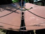
  • I welded a series of temporary protruding long lugs to the bottom edge of each plate to prevent one slipping under the other and to stop them from flopping over when placed on the cradle.
PICT0789.jpeg
Unknown.jpeg

PICT0798.jpeg
PICT0795.jpeg
PICT0803.jpeg
PICT0794.jpeg

Using these newly discovered techniques my confidence was regained; and I was now ready to tackle the remaining plates.
 

Attachments

  • PICT0798.jpeg
    PICT0798.jpeg
    97.2 KB · Views: 4

JOHNPEET

Well-known member
Joined
24 Sep 2002
Messages
459
Location
Anglesey
Visit site
The Bottom Plates

The four bottom plates are the biggest of all the plates and weigh around 500kg each. They are each up to 6m x 2m in size and made from 5mm steel plate whereas the rest of the plates of the boat are 4mm.

View attachment 146422

The first job was to place these four plates on the cradle allowing them to form the shape provided at each of the three resting stations formed from the erected castles. Each bottom plate makes up a corner piece of the bottom hull with a 1mm gap between it and its two neighbours - thus forming a 1mm cross gap in the middle of the hull to allow full penetration welds at these critical points. Sounds easy enough!? Hm!

It is true to say this is the only point in the build that I briefly doubted myself and wondered whether I had in fact embarked on something beyond my experience and capabilities!

The challenges I came across were numerous:
  • Each bottom plate weighs about 500kg so is impossible to move by hand
  • Initially I really struggled to fully cope with the handling characteristics of plate. I was, up until then, used to handling wood which if moved one end, was sure to provide at the opposite unsupported end an equal and opposite direction of movement!
  • There seemed to me to be a fundamental design flaw in the cradle in that there is only three supporting stations. This means that the two front plates were relatively better supported as they rested on two stations but the aft (heavier) two rested on just the one station. The result of this was that when first placed in position, the plates just flopped over either side of their respective supports - a particularly pronounced problem for the rear plates.
  • The cradle stations form a ‘V’ shape to help form the bottom shape of the hull at that respective point. Particularly at the front, the ‘V’ is quite pronounced. The problem comes as each “V’ support is left open at the bottom with a big gap in order to allow access for welding the central longitudinal seam. Of course, that then means each plate when placed in the cradle, slips down towards the centre and is in doing so becomes impossible to butt against its neighbour.
  • Even when the plates were eventually prevented from slipping out of position in relation to each other (as detailed below) it just seemed as if they had been cut to the wrong shape and would be impossible to make them come together.
View attachment 146423
View attachment 146424

After a lot of thought, trial and error and perseverance, I developed the following techniques to manoeuvre the plates to get the perfect positioning and fit. These may well be recognised as standard fitter practices but unfortunately I had to find them out the hard way!
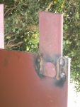
  • I welded temporary lugs onto the surface of plates to allow the block and tackles suspended from the gantry, and other places, to be attached at different places, to give lift or pull as necessary. Together with jacks and wedges against the floor walls and other fixed objects it was possible to help position the plates. Thus, the limited working space for the build wedged between my workshop and elevated garden wall and shrubbery actually proved very advantageous as there proved plenty of fixed objects to lever against.
  • I welded staggered temporary notched lugs to the surface of adjoining plates which allowed a crow bar to lever one against the other to perfectly align.
  • I welded a series of temporary protruding long lugs to the bottom edge of each plate to prevent one slipping under the other and to stop them from flopping over when placed on the cradle.
View attachment 146425
View attachment 146426

View attachment 146427
View attachment 146429
View attachment 146430
View attachment 146431

Using these newly discovered techniques my confidence was regained; and I was now ready to tackle the remaining plates.

I remember one of the golden rules to be applied when assembling, struggling to manipulate and tack weld plates together - “If the plates don’t appear to fit, you’ve done something wrong!” …….and I have to say that apart from a couple of instances where there were very obvious errors in the cutting or folding of parts, the accuracy of the CNC plasma cutting was amazing - absolutely millimetre perfect!
It was just a case of fighting with the plates to get them into the correct position where they just came together!

it’s like ”deja vu“ reading this! ??
 

Dufton

Member
Joined
26 Aug 2018
Messages
46
Visit site
I remember one of the golden rules to be applied when assembling, struggling to manipulate and tack weld plates together - “If the plates don’t appear to fit, you’ve done something wrong!” …….and I have to say that apart from a couple of instances where there were very obvious errors in the cutting or folding of parts, the accuracy of the CNC plasma cutting was amazing - absolutely millimetre perfect!
It was just a case of fighting with the plates to get them into the correct position where they just came together!

it’s like ”deja vu“ reading this! ??
Yes it was made very clear from the “instructions” supplied and from my supplementary research that no matter how impossible it at first seems, the plates will fit together and the accuracy of the cnc cutting shouldn’t be challenged. Under no circumstances should the plates should be cut to make them fit - any mistakes will be the builder’s and not from inaccurate cnc cutting. I agree with you that on the whole the cutting was indeed perfect. However, with this golden rule on my mind, there was one area around the swim platform later on in the build that I really struggled with and this did lead to a complete halt in progress and a few weeks of head scratching, multiple re-checking of measurements etc. When located in their correct marked positions against the bottom plates and rear stern plate, the hooked shaped longitudinals forming the swim platform shape just seemed too high to allow the swim platform top plate (and subsequent stair assemblies etc) to properly fit. I eventually spoke to Bruce Roberts himself - who I have to say was very approachable and helpful - and after some checks his end it transpired that there had been some recent design changes made to the swim platform stairs and this had impacted on some of the surrounding areas and those design changes had not completely been followed through to the cutting files! So my instructions as a work-around from BR was to cut 20mm or so off of the top edge of each of the hooked longitudinals. Although frustrating, it was actually a great relief to me to learn that I hadn’t myself messed up and that I didn’t after all have to dis-assemble any of the previous work I had done.
 

Greg2

Well-known member
Joined
24 Jun 2002
Messages
4,464
Visit site
Having done quite a lot to our boats over the years and knowing how much effort is involved I am in awe of anyone who does a self build like this. JOHNPEET’s story was incredible and this one is following in that vein, particularly when the starting point was no experience in welding or working with sheet metal!
 

Dufton

Member
Joined
26 Aug 2018
Messages
46
Visit site
Having done quite a lot to our boats over the years and knowing how much effort is involved I am in awe of anyone who does a self build like this. JOHNPEET’s story was incredible and this one is following in that vein, particularly when the starting point was no experience in welding or working with sheet metal!
Those are very kind words, thank you. Of course I am very very proud of the end result and I get an immense amount of satisfaction and pleasure being on board and enjoying the fruits of the years of my labour. As I have said before however most tasks can be broken down into smaller parts which are achievable by most practical people. What I guess proves the most challenging aspect for many with big projects like this is being lucky enough to have continuing favourable circumstances (family support, resources etc) and the necessary tenacity and ability to endure all the ups and downs of the long journey. I certainly couldn’t have completed it without the brilliant support, help and encouragement of my family and friends and the real credit must go to them for putting up with my project in their lives for so long!
 

Dufton

Member
Joined
26 Aug 2018
Messages
46
Visit site
Longitudinal stiffeners

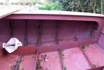
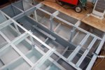
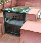
Two main 10mm thick longitudinal stiffeners which also act as supports for the main engine bearers, together with some thinner supports were next tack welded to the bottom plates in the positions pre-marked on the bottom plates.
2003-07-25 20.00.17.jpeg

Web frames

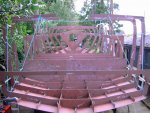
The boat is made up of 15 shaped web frames placed at 750mm centres along the longitudinal length of the bottom plates and longitudinals.

Each web frame is made up of several parts which were initially tack welded together on a completely flat surface (I used several sheets of 18mm ply screwed side by side on supporting pallets on a flat concrete floor) before lifting and placing in one piece onto the bottom plates and longitudinals. The dimensions of the finished frames are absolutely critical as most of the other main plates are joined to them; and as such they determine the cross sectional shape of the boat at each point, and hence its overall ‘fairness’ . The dimensions must be checked and double checked and checked again. Even small inaccuracies in the frames could significantly affect the build as they can compound and multiply as the build progresses.

PICT0821.jpeg

To help prevent distortion and to give support when lifting and positioning, I found it useful to temporarily tack-weld some ‘T’ section profile to the assembled frames at critical points.

PICT0822.jpeg
PICT0824.jpeg
PICT0826.jpeg

Starting with the middlemost and working backwards and forwards from there, the assembled web frames were lifted and slotted over the longitudinals. The bottom plates were then lifted and adjusted as necessary towards the frames until they fitted accurately and snugly and the frames and bottom plates were then tack-welded into their correct and final positions.

PICT0884.jpeg
Unknown.jpeg


Stringers

Next, the stringers (inter frame supports) were placed in the slots of the web frames on the sides and again tack-welded at a few positions to keep them in position.

PICT0888.jpeg
 

Dufton

Member
Joined
26 Aug 2018
Messages
46
Visit site
Side plates

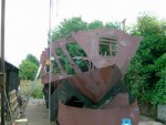
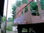
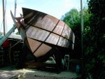
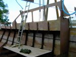
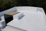
Using the gantry and a plate clamp (brilliant piece of kit!) attached to a block and tackle, the side plates were then put into position by making sure the plate was more or less in balance when it was hanging in the air, and then bringing it to its allocated position. Using improvised wedges such as lengths of wood against the workshop/garden wall and/or a hand winch attached to other parts of the boat, a localised end point of the plate was put in the right position and tack-welded. This process was then continued along its length by moving the plate up or down a bit with the block and tackle and tack-welded, until the entire plate was in the correct position and had been tack-welded. Some of the tack-welds had to be adjusted as the plate positioning progressed, and some tack-welds were also placed on the uprights of the frames, again insuring the plates were snugly touching everywhere and against the marks pre-etched on the plates. My research had emphasised that if the plates were not fixed snugly and actually fully touching the longitudinals and frames, distortions were more likely during the final welding process, creating what is called a ‘starved cow look’ and which is all too often observed on steel hulls. Using this method I found that all the plates could be handled and tacked in perfect position completely single handedly. The whole process for each main plate took about a day to complete and so this was quite an exciting time as the final hull shape relatively quickly evolved.
PICT0891.jpeg
PICT0897.jpeg
2003-10-26 16.29.57.jpeg
PICT1037.jpeg

Transom, stern plates, stairs and swim platform

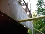
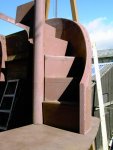
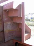
As I have mentioned before, the design of the swim platform steps had been improved by BR just prior to my purchase of the cutting files and plans but the designers had only updated these changes on some but not all of the drawings. The changes, and hence the inconsistencies in the drawings, was not documented or at all initially apparent. Indeed, it did mean that some of the plates destined for that area had been wrongly CNC cut and just did not fit. This was very confusing and quite a bit of time was spent checking and rechecking dimensions and drawings to identify what I had assumed then to be errors in my assembly. I finally spoke to BR and after checking things their end they identified the problem and suggested a fix. This basically involved removing the hooked shape stern longitudinals which had already been tack-welded into the assembly, and then cutting them down on their top edges before refitting so as to provide a lower and more level surface for the swim platform and stairs to be built up from. The plans error also meant that I had been supplied with some wrong sized pipe from which to form the tightly curved newel posts of the stairs at either side of the swim platform. Annoyingly, this caused further delays as the new correct size pipe turned out to be a non-standard stock item. It also needed to be supplied pre-primed with a weld through primer which led to even more delay.

PICT1404.jpeg

PICT1419.jpeg
PICT1405.jpeg
2005-10-31 15.19.37.jpeg

PICT1409.jpeg
PICT1416.jpeg
 

Attachments

  • PICT1404.jpeg
    PICT1404.jpeg
    76.8 KB · Views: 2

Dufton

Member
Joined
26 Aug 2018
Messages
46
Visit site
Awesome! All that needs to be said. D
Thank you for that - very good of you, and others, to take the trouble of saying so! Everyone on here has been very positive which is so nice as in contrast, soon after launch, I posted some pictures of the vessel on another site and all I got was criticism!
 

Bouba

Well-known member
Joined
6 Sep 2016
Messages
42,684
Location
SoF
Visit site
Thank you for that - very good of you, and others, to take the trouble of saying so! Everyone on here has been very positive which is so nice as in contrast, soon after launch, I posted some pictures of the vessel on another site and all I got was criticism!
I don’t know why people do that....except that a lot of our members are on other forums ????
 

Dufton

Member
Joined
26 Aug 2018
Messages
46
Visit site
Folding and Bending

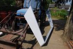
Most of the bending of the plates to make the required hull shape was done whilst manipulating and tack-welding them in position. However where this was not possible due to the tightness of the curve required, the plates had to be bent before positioning in a heavy duty fabricators’ folding press. The plates to be bent were all 4mm stock.

Included in the drawings is a plate bending schedule. This details the position and radii of the necessary bends. The surface of the plates themselves were also etched with folding marks during the CNC process. The plates that had to be independently bent were:
  • Swim platform steps
  • Swim platform steps surrounds
  • Radar arch uprights
  • Forward wrap-around surrounds of the flybridge
  • Bow cone
  • Rudder skin plates
PICT1429.jpeg
PICT1462.jpeg2008-07-28 12.02.37.jpeg
image.jpeg

In addition to these I arranged for some other bending to be done on some plates that I had separately provided to complete some modifications I required on various areas of the topsides (as detailed in the next post).
 

Dufton

Member
Joined
26 Aug 2018
Messages
46
Visit site
Did you doze off?‍♂️?
Haha! Nah, was trying to add another post but it got all confused (or I did!) and ended up with a real mess! Decided it was best to try to delete but couldn't work that out either so just edited it to two random letters! Anyways, I'll try again.......
 

Dufton

Member
Joined
26 Aug 2018
Messages
46
Visit site
Topsides

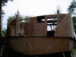
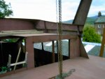
After the side plates and transom areas had been finally assembled and tack-welded, the plans called for supporting strips to be dropped in and tack-welded into the top of the web frames and the subsequent fitting of the side deck areas and cabin roofs to complete the hull’s basic envelope shape.

This would all have been reasonably straightforward and quick had it not been for the fact that I had decided to make some extensive changes and improvements to several areas of the topsides:
  1. Firstly, I was also keen to make several changes to the area of and around the flybridge:
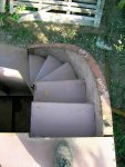
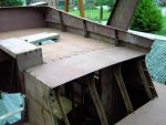
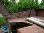
  • The BR plans showed quite a short and stunted design at the rear end of the flybridge with a simple tubular ladder type access. Aesthetically, being very angular I felt this odd, and would also result in severely limiting the flybridge’s practical use beyond just helming. I decided I wanted the flybridge as a larger area to incorporate extensive comfortable combined seating and storage units which would also be capable of lying down on for sunbathing. I also wanted to incorporate a small drinks table, a kitchen area with bbq, sink and fridge and of course the top helm station itself. As I have previously worked with fibreglass, the plan was for me to custom make these units in my workshop. I also redesigned the rear area across the back of the flybridge to incorporate a flared curved back plate and I fabricated some curved faced metal stairs for easy access.
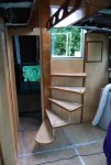
  • The BR suggested companionway access and straight stairs leading down into the salon would have further restricted the usable flybridge area and also would have significantly restricted the internal salon area. I therefore decided to incorporate a quadrant shaped top companionway door with an open quarter turn spiral staircase leading down into the salon which allowed better use of the available space both on the flybridge and in the salon.
  • From my research it was apparent to me that the flybridge area would be treated as an enclosed deck for RCD and MCA Coding purposes, (both of which I wished to comply with) and hence would necessarily require a raised combing around the companionway. The BR suggested design would also give significant headroom issues when entering to go down inside the boat. My solution was to fabricate a suitable quadrant combing and to fix the top companionway door to the top of this. To one side of this raised combing I also extended it starboard which then allowed a comfortable headroom when entering and then descending to the top treads of the spiral staircase down into the salon.
  • The aft deck is some 650 mm lower than the flybridge (and hence the corresponding aft cabin ceiling is 650mm lower than the salon ceiling). As a result, internally, the designed headroom for the access door through the bulkhead into the aft cabin would have been less than 1.2m! With my proposed engine room layout under the salon floor, I knew it would be impossible to section out into the engine room to accommodate access stairs leading down into the aft cabin and so I felt this arrangement was really unsatisfactory. My answer was to add a raised backwards extension to the flybridge which correspondingly gave increased internal headroom leading from the salon into the aft cabin and also enough headroom for stairs to be built within the aft cabin itself. This solution included the construction of a small semi-circular landing to allow me to position the aft heads at salon floor level, also to be accessed from the new landing.
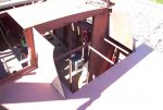
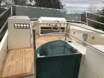
  • Engine removal hatch. To my astonishment I came to understand that it was normal industry practice to build engines, generators and fuel tanks etc into a vessel during the course of it’s construction, without creating any special access arrangements to ever allow easy removal and replacement of them at a later date if the need should ever arise. I had understood that in those circumstances, it is normal for access to be created by cutting a hole in the side/top of the craft. No matter hard I tried, I just wasn’t comfortable with the contemplation of ever doing that to my creation, so I designed an access hatch through the floor of the flybridge which could be exposed, unbolted and then removed if ever needed. The plan also involved modifying some of the frames around the engine room below and the longitude supports of the flybridge and salon floors, by incorporating additional bolt together sections.

A challenge which became a recurring one throughout the build became first apparent when embarking on these changes - there is no datum or reference point to work from as you would in the normal way in order to check the accuracy of anything. This is because:

a) There is no way to accurately ensure the bottom plates (and hence the hull build up from them) is level in any direction on the supporting trestles.
b) Even if the hull were positioned completely accurately on the trestle supports, there are so many choices and variables in the build affecting the vessel’s final weight and distribution, and hence it’s waterline level, that nothing constructed can be said to be, or remain, completely level or upright!
c) Also, much of what is additionally constructed is fabricated up from, or continued out from, curved or sloping surfaces, and much of it itself therefore having to continue with that curved or sloping surface.

As a result, much of what was added had to be done by eye and judgement and without the usual reliance on any datum or using any normal levelling methods.

2004-07-11 22.09.53.jpeg
2006-07-19 15.23.57.jpeg
2004-09-17 22.29.35.jpeg
2008-07-28 12.05.47.jpeg
PICT1447.jpegDSC_0117 (1).jpeg
Picture 179.jpeg
2008-07-28 12.06.23.jpeg
DSC_1518.jpeg
2009-05-20 14.48.52.jpeg
IMG_4055.jpeg
IMG_3998.jpeg

Alterations continued on next post..........
 
Top