Lithium 304Ah Build

gregcope

Well-known member
Joined
21 Aug 2004
Messages
1,595
Visit site
Hi All

I thought I would document my Lithium build and share. This thread is inspired by Poey50’s thread. Thank you @Poey50!

Our sailing is coastal and we like nothing more than staying at anchor for days, exploring and relaxing. We had 250Ah of cheap Flooded Lead Acid house batteries and 360W of Solar, a usable capacity of 125Ah. If it is sunny we are self sufficient, just. Our main consumers are the fridge, charging iDevices add instruments & ram autohelm when sailing. Even with everything on we seem to only draw about 30A, mostly it is around 10A when sailing and 4A ish when just the fridge. Usual draw is around 30Ah per day. I wanted to increase capacity to cover grey days as well as more laptop use (WFB; Work From Boat!). I was going to add another 125Ah FLA.

I have been looking at Lithium for nearly two years as it seems to offer many advantages;
  • More usable capacity (80-90%) compared to FLA (50%).
  • Much better charging efficiency compared to FLA; 99% compared to 85%. Ie if you put 20A in, that is what the battery can give back. Compared to FLA that will only give back 16A.
  • Low internal resistance that allows LifePo4 to accept lots of amps (ie 0.5C, or around 152A for 304Ah cells)
  • Not having the 80%+ SOC drop in charge rate that FLAs have. This and the ones above effectively means any charging (like Solar) becomes much more effective.
  • Much higher energy density (smaller and lighter than FLA); 250Ah of FLA is 56Kg, 304Ah of LifePo4 is 16Kg and half the volume.
  • Much longer life (with care well over 10years+) compared to 6 years (ish) with FLA.
  • Prices appear to be comparable, or cheaper for capacity over lifetime now.
Some disadvantages;
  • Often higher initial cost.
  • If going DIY risks of purchasing from dubious sellers.
  • DIY assembly mistakes.
  • Most charging and monitoring sources need review and reconfiguring or changing.
  • Issues with Alternator and BMS disconnect.
  • Battery complexity & reliability could be an issue.
  • Cells are fragile and affected by temperature. For example charging below 0c will severely damage them. Along with over / under charging.
  • Cell life is affected by warmth, even 45c affects life.
Nordkyndesign has a good comparison of pros/cons on this page. I would encourage anyone to understand the tradeoffs with Lithium. I remain unconvinced about “Drop in replacements” due to the fundamental differences. This is specifically around charging regimes that are aimed to keep FLA going whereas LifePo4 requires significantly different settings.

Things came to a head this year when one of our house 125Ah FLA cooked itself. I decided to go to LifePo4. There are various different decisions to make. Drop in replacement vs DIY; Which cells; Which Battery Management System (BMS); How to deal with the Alternator ; Charge profiles and where to get it all from.
 

gregcope

Well-known member
Joined
21 Aug 2004
Messages
1,595
Visit site
DIY or purchase

I looked at various “Drop in replacement batteries”. I think the BattleBorn are particularly well engineered and are used by SV Delos as well as Sailing Uma. Battelborn underrate the Ah capacity as well as secure the cells really well. These should perform for a long time. However they are around £1000 per 100Ah. Victron also look good, similar prices. There are cheaper alternatives, however looking at Will Prosse youtube teardowns many are very simply engineered with little hope of warranty backup. Hence I decided to DIY. I have a good understanding of electrics, crimping etc. and have done a lot of research...

There are various online Marine guides to LifePO4. nordkyndesign.com has lots of resources around LifePo4. However I find it verging on the religious as it set very high standards that are not applied to FLA. For example FLAs do not have a BMS to protect them from user error, or low discharge warnings. Some are also quite tricky to achieve (ie linking charging sources to the BMS). The one area I am diverging is separating charge and discharge circuit. So although I respect lots of the ideas I will not be adhering to all of them! I must be an LifePo4 heretic.

Marinehowto (excellent marine resources) also has a very long page on LifePo4; Worth a read. DIY Solar Power with Will Prowse has lots of videos on LifePo4. OffGridGarageAustralia is fun and informative. Poey50’s thread on YBW has lots of good info. Diysolarforum.com also has lots of threads. The Digital Mermaid, Ray Builds Cool Stuff and LithiumSolar are also worth looking at for some topics.
 

gregcope

Well-known member
Joined
21 Aug 2004
Messages
1,595
Visit site
Which cells

I liked plastic encased Winston cells, however these are nearly double the cost of the Blue Ali-cased prismatic cells. I would go that route if slightly cheaper as the Winstons look robust and have a slightly different chemistry that allows charging at lower temperatures. I decided on Eve cells. I researched suppliers which is a bit of a minefield as there are lots of grey sellers on Aliexpress, Amazon, Ebay or Alibaba who are selling older, used or damaged cells repackaged, without any history. Lost of stories or videos about bloated cells or those that do not achieve capacity. Its a minefield!. After researching on Diysolarforum.com I decided to go with Amy from Luyuan on some new, balanced, matched cells with testing data.

During the ordering process I enquired about 300+Ah cells. These are the same size as 280Ah cells and only slightly more expensive. I decided to go with these 304Ah, the capacity report suggests they all have over 320Ah. Even if they do 304Ah, they should give 10% more capacity for the same physical size at less than 5% price difference.
 

gregcope

Well-known member
Joined
21 Aug 2004
Messages
1,595
Visit site
Which BMS

Battery Management Systems (BMS) are designed to protect the expensive cells. They disconnect on high or low cell voltage. Ie prevent over charge or discharge damage. Most also balance cells to try and keep them the same capacity and help prevent a “runner” from causing a disconnect. The way they enable/disable connections falls into two camps; Some are common port (discharge/charge) some are spit. Some control relays/contactors, others use Mosfets. Some allow changes of settings, others do not. Some have bluetooth apps to expose settings and allow changes, some do not. Some have RS485 ports that can also talk to Victron kit.

I looked at BMS123, Orion and electrodacus and to be honest went round in circles, specifically around the parts required, poor instructions, or total prices. Lots of people disparage Mosfet based BMS as unreliable, but I find that mostly hearsay as Fridge compressor controllers are Mosfet based and can last decades. If not driven constantly at their limits they should be very reliable. Relays based BMSs’ confused me as I could never find a simple answer of “get relay XXX”. Another concern was the power draw of a relay itself as our use is intermittent (not live aboard) quiescent power draw is an issue. Cost also a factor as some are significantly more expensive than others.

Along my travels I discovered the Overkill Solar 120a BMS, which is a repackaged JBD-SP04S020 BMS they tweak, test and resell. They have a great manual and support. Will Prose and others on Youtube seem to use them with success. I ordered one of those that arrived in three days from Florida. I also ordered some 120A JBD BMS from China on Aliexpress.

The JBD-SP04S020 has a Bluetooth app that allows settings to be changed (more on that later) as well as Low/High temp disconnect. Being Mosfet based they are small compared to relay based ones. The biggest compromise is that they are a “common port” BMS which means both charging and discharging are combined. Using a common port BMS you need to be able to manage BMS disconnect for charging as well as load.

I like carrying spares. Having been caught out in the past and ending cruises without them I carry things like a spare starter or alternator. I intend to carry a spare BMS. Another plus of the JBD ones is they are inexpensive compared to many others. In terms of what is likely to fail on a pack in a ten year life I would expect the BMS to be high on that list!
 

gregcope

Well-known member
Joined
21 Aug 2004
Messages
1,595
Visit site
Alternator

Most Alternators pose an issue for LifePo4 systems for three reasons. If the BMS disconnects to protect the cells this creates a large voltage spike usually followed by the Regulator burning out. The other issue is that the very low internal resistance allows LifePo4 to accept very large charging Amps that can make simple Alternators burn up as they try to supply max output constantly (victron video here). Thirdly LifePo4 has as different charge profile to FLA (ie lower voltages).

There are a few ways of solving the Alternator issues. Replace the Alternator with a Smart one (e.g. Balmar) that monitor alternator temp as well as having Lithium profiles is one. They can avoid the disconnect or burnouts. These are expensive but great for those who want to charge their LifePO4 banks hard. We do not do this and rarely run the engine to charge. Plus we have a spare Alternator. Another approach is to separate the banks so that your LifePo4 is charged separately with a B2B charger off an FLA Starter battery that accepts alternator output. I have gone this way with a Victron Orion-Tr Smart DC-DC Charger 12/12-30 (360W). If I was going round the world sailing I would get a Balmar Smart Alternator system (with spares). That would nearly triple our install costs.
 

gregcope

Well-known member
Joined
21 Aug 2004
Messages
1,595
Visit site
Cell target voltages vs lifetime

LifePo4 cells can last a very, very, very long time. Satellites apparently last 40k cycles using 20% of their capacity (between 40% ~ 60% SOC). I intend to use 80% of the capacity and give them an easy life. Charging profiles seems to be a dark art. As BMSes cut out at high and low cell voltage, having a balanced bank is a good idea to extract maximum capacity; Otherwise a high or low cell can trigger a BMS disconnect. Most BMSs do cell balancing. Passive ones burn off charge from high cells when charging. Active ones charge low cells from high cells. Many only balance at high states of charge, e.g 3.5V per cell or 99.7% SOC. So you want to aim for your cells to be balanced whilst not over charging.

I will change the BMS to balance at 3.4/13.6V (cell/battery i.e. 92% SOC). Charge sources will go into an absorption for 2hrs to allow balancing. This will drive up the charge %, how far depends on charging Amps available.

I will set a low voltage alarm on our BMV-700 Victron battery monitor at 3.2V/12.80V (20%). The BMS will low voltage disconnect at 3V/12.00V. That is a 10% SOC difference which on these packs is around 30Ah. Which is around a day on our normal use so should be enough warning. High voltage will probably be at 13.65V.

Another complexity of charging profiles is that LifePo4 packs have the longest life when stored at mid stages of charge (50%). This poses a problem when boats are left (moorings/marinas) as they will drift upto 100%SOC during the week left unused but on chargers. I intend to have two Victron profiles, “Use” and “Storage”. The former will drive up the SOC, the latter will aim to keep around 50% SOC (3.27/13.08V). For most of the year I will leave it in Storage mode and only reset to “Use” mode for the longer sails. Victron makes this reasonably easy to swap.

Another thing to consider is temperature. LifePo4 does not like being charged below 0C. This is a problem for Camper Vans / RVs used in winter. Less of an issue for boats in non-polar conditions. They also last longer if not kept warm. Ie 45C or above. See Cell data sheets. This is less of a concern in the UK. Avoid keeping them in engine rooms without monitoring temperatures and ventilation.
 

gregcope

Well-known member
Joined
21 Aug 2004
Messages
1,595
Visit site
Build

Our boat has, like many, a dedicated battery box. This consists of a box (without lid) within a locker (that has a lid). The locker is ventilated top and bottom. Within this locker connections goto a off-1-2-Both switch on the positive feed and within the locker is a Victron BMV-700 shunt. The box had an 80Ah Gel engine start battery and two 125Ah X31 sized lead acid batteries. The box is around 340mm wide, 1000m long and 250mm high (to the bottom of the locker lid woodwork).

Most drop-in-replacement batteries replicate the standard lead acid sizes. Although they tend to be taller and/or longer. Many LifePo4 cells at higher capacities are taller than the standard size. Our battery box needs a careful selection of cases.

I did a long search to find a battery box that would fit the 280/304Ah cells (there is only around 2mm difference in height) within our battery box. There will be a new negative bus bar(s) for all the batteries, then a shunt and finally all the negative loads that terminate “on the battery” like the VHF, Bilge pump and a mains charger. Our windlas also connects via a 70A breaker and do not go via the off-1-2-both switch/main bus bars.

Cells expand (thicker by 1mm) as they charge. There is much discussion online on “bulged” cells as this can become permanent. Recently Eve, one of the manufactures of the prismatic aluminium clad cells, changed their data sheet to show increased cycle life (from 2500 to 3500 cycles) if the cells are compressed by 300kgf. This has generated significant online discussion. Some people do not bother, as 2500 cycles is sufficient. Others compress using tape. Some compress using threaded rod into end plates (usually plywood). Others get complex with springs. I intend to take the middle ground and compress with tape. This will be done when the cells arrive at their 30% state of charge.

This battery will store nearly 4kwh when fully charged. This is a lot of energy. The risk of a fire or other damage from a short circuit is significant. There are two factors to consider; What size of fuse and the reaction time of a fuse. Many drop-in-replacement have no fuses which I think is a risk. In terms of sizing the 35mm2 cable is rated at 240A. The BMS is rated at 120A. There are various different calculations (e.g Bluesea). I have chosen a 300A fuse. Now the next thing to consider is the reaction time. A lifePo4 cell can discharge very significant energy very, very quickly (>20000A). There are issues with some fuses (ANL/Mega) melting themselves open. See LiFePO4 Batteries On Boats - Marine How To for more details. Hence I decided to fit a T-class fuse which are good in this context. These are hard to come by in the UK and not cheap. This fuse is placed near the main battery positive post to protect the main positive. So a note my ratings are all well above the BMS rating (120A) and should easily cope with peak load for hours.

Now I got a bit carried away on crimp lugs. Many seem to be, to me, quite small in terms of mating surface area or lug wall thickness. Having purchased many different brands I settled on Klauke. Purchased from RS (e.g. M6 for 6mm). I also found my crimper lacking when doing these. The jaws would bend and not align correctly making an odd crimp. I purchased a yellow eight ton hydraulic one from Ebay. Makes a nice crimp if a little tricky to align everything. I also use 3:1 adhesive lined heatshrink. A tip I picked up from many hours of youtubing is to clean the cable insulation before applying to remove the mold release agent often left on the cable insulation.

I initially wrapped the cells with strong packing tape. Between each cell I placed some 1mm cutting board (ebay) as an extra insulator as I do not trust the blue heat shrink longer term. On the ends I used 1.5mm GX10 Glass Fibre boards. I am thinking of going thicker as these do bend. I made a rubber impact protection from some leftover roof 1.5mm EDPM and also tapped that. With this EDPM my cells are as snug fit.

You might be wondering why there are M20 Glands and the battery positive / negative lugs have been removed. This is for two reasons. Firstly my battery box is too shallow to use them (they hit the lid). Secondly they protrude down quite far inside the lid. I removed the plastic with an oscillating tool and then used a soldering iron to melt/remove the copper terminals out of the plastic. The hole is filled with PU40 polyurethane sealant from toolstation. The lugs are for 35mm2 tinned cables that will terminate in an SB175 Anderson plug to allow me to disconnect the batteries.

I made balance leads from 6mm2 cable and M6 lugs as well as some temp 6mm2 leads to charge / discharge test connected via XT60 connectors. I can connect the charger via the XT60 and then swap to the capacity tester. This avoids touching the battery terminals.
 

gregcope

Well-known member
Joined
21 Aug 2004
Messages
1,595
Visit site
Top balancing

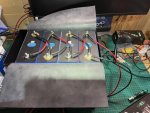
I also purchased a Constant Current, Constant Voltage (CCCV) 30W desktop power supply. I used this to top balance the batteries using the balance cables. You might notice the cells were arranged / taped in their final series configuration hence the balance cables going over each other. Top balancing 304Ah @10A took days. I targeted 3.4V then 3.5V then 3.6V. It was interesting to note the final section of going from 3.6V to 3.65V was very quick.

If doing this again I would spend a little more on a CCCV PSU that had a finer control of the voltages or current. The analog dials are tricky to set. I would also get a more powerful one if not too much more expense to cut down on charging time.
 

gregcope

Well-known member
Joined
21 Aug 2004
Messages
1,595
Visit site
12V assembly

I left the cells charged at 3.65V for 12 hours and then reassembled into a 12V pack using the supplied copper bus bars. One video from Ray (builds cool stuff) highlighted how to make good cell connections so I followed that which is essentially;
  1. Measure bus bar resistance along its longest edge to ensure you have copper ones and not brass (ie 10miliohm)
  2. Drill/Tap M6 holes for BMS/Balancer cables on the bus bar and de-bur edges
  3. Cut one bus bar in half and add two M6 tapped holes in each end for the main +/- connections to the BMS and balancer
  4. 600grit sand the tops of the terminals - I used a 6mm spacer to ensure this was flat
  5. Use gloves to avoid skin oil from fingers
  6. Clean terminals/bus bars with isopropyl alcohol
  7. End sure bus bars are flat
  8. Assemble with carbon grease and use a torque wrench - 6nm
  9. Measure resistance between terminals - aim for 15 miliohm
  10. Repeat if your not getting that target
 

gregcope

Well-known member
Joined
21 Aug 2004
Messages
1,595
Visit site
Testing

I purchased a 180W capacity tester from Banggood. Due to supply chain issues it took around four months to assemble the first pack, upon which, I discovered that this mine only ran up to 4A (instead of around 14A). Ordered another off Amazon which worked above its rated 150W capacity, ie it seems like a mislabeled 180W version.

I decided to do capacity test at 12 Amps. Although this battery/BMS can do upto 120A this better reflects my duty cycle and is 10% of the BMS capacity. I do not yet have a large inverter to be able to do higher C rate tests.

Initial tests showed 311.78Ah which compares favourably to the 304Ah rated capacity (+2.5%). Cell three had triggered a “Cell undervoltage protection” BMS cut off at 2.5V. Other cells were 2.824V, 2.883V and 2.719V. Peak temperature was 23.5C according to the BMS, on the Mosfets. Using a Thermal camera no parts of the battery were above that. At this low C rate this is to be expected. Two more capacity tests gave the same results (312Ah).

I was surprised at the very flat discharge curve. You can check often and see no change in the cell voltages, even though it has discharged 20Ah or so. The tests take 25hrs. Recharging @10A a day and a half!
 

gregcope

Well-known member
Joined
21 Aug 2004
Messages
1,595
Visit site
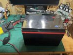
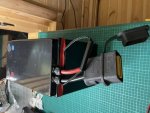
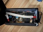
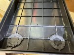
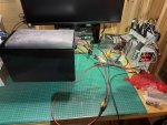
Some pictures. In a great British tradition this is shed engineering;

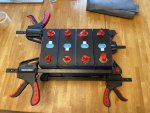
Ontop of the Power Supply (top right of some pictures) is my first prototype;

311225DE-4239-4258-A255-7A868D8A25C4.jpegD9957527-4923-4858-9CA4-ED3EA97D3FF6.jpeg62192A0D-25E1-4564-8EF7-FA380FB97F74.jpeg38106AAF-C686-4758-AB61-44DC1752B64D.jpegA9073B59-2D14-42A6-81FD-91BCE07322E7.jpegA096B6B1-7ED1-44E6-B5DF-3FFB1EE89563.jpegA8717FA1-DA60-4D4A-96AF-DF47A4DC4915.jpeg3D128DA3-BAD2-4ECA-93F4-40832E72D080.jpegF203394E-6DFC-40B3-A32B-38BDCD095D08.jpegC4084190-DF53-48EE-82D2-E2EC829468A1.jpeg
 

roaringgirl

Well-known member
Joined
1 Nov 2014
Messages
886
Location
Half way around: Wellington, NZ.
bit.ly
I just finished a 400Ah LiFePO4 installation to replace 540Ah of AGM.

I chose Victron and managed to do the whole thing for roughly £5k. Having most of the components bluetooth monitorable/configureable with the same android app is a bonus.

Alternator: I used a Balmar external regulator as shutting off the power to the regulator gives a graceful alternator shutdown and it is programmable for Li charging.

Solar: I used Victron MPPTs with a specific Li charging profile

Wind: I have yet to successfully update the Rutland regulator to its Li profile. The software crashes and fails to update the box, I need to find a windows7 PC to complete this successfully (I think).

Hydro-generator: I reconfigured the watt and sea charge profile for Li

Invertor/shore charger: I have an ancient Victron phoenix multiplus. After some research I managed to allow the BMS to control it with some relays and a Victron BatteryProtect.

Split Charge/Load: these were already split, I put relays between each charge source and their charge regulator (and one to switch the Balmar off). All these relays are controlled by the BatteryProtect wired into the BMS. I have Cyrix relay ordered so that the BMS can switch off the load too.

Outstanding issues:
1) when the relay detaches the wind-gen from its regulator, the wind-gen goes into free-spin rather than braked-mode. I need to figure out a way for the BMS to tell the regulator to brake the turbine instead.
 

gregcope

Well-known member
Joined
21 Aug 2004
Messages
1,595
Visit site
@roaringgirl your setup sounds great.

how do you find the watt&sun?

i am jealous of the victron kit.

I was re-reading your improved soft shackle guide yesterday! I did make some “normal” ones mind as I do not need the strength.
 

vas

Well-known member
Joined
21 Jun 2011
Messages
7,915
Location
Volos-Athens
Visit site
Cells expand (thicker by 1mm) as they charge. There is much discussion online on “bulged” cells as this can become permanent. Recently Eve, one of the manufactures of the prismatic aluminium clad cells, changed their data sheet to show increased cycle life (from 2500 to 3500 cycles) if the cells are compressed by 300kgf. This has generated significant online discussion. Some people do not bother, as 2500 cycles is sufficient. Others compress using tape. Some compress using threaded rod into end plates (usually plywood). Others get complex with springs. I intend to take the middle ground and compress with tape. This will be done when the cells arrive at their 30% state of charge.

Greg, how is one meant to measure the 300kgf clamping force?
I'm going to be using 4 M8 threaded rods, washers and nuts. I even have a torque wrench :rolleyes:
now what?
 
Top