Electric Schematic

Ian_Edwards

Well-known member
Joined
9 Feb 2002
Messages
1,906
Location
Aberdeen Scotland
Visit site
Hi,
I've revamped the electrical system on my Southerly 46RS this winter.
This is a schematic of the layout. I haven’t included DC fuses. It's just the general layout.
There's has been quite a lot of input from the forum over the winter, so thanks for that.1000010364.jpg
The AC side start with a 16amp RCBO, I haven’t included a galvanic isolator. The boat spends very little time in a marina, just few days ayear. This is followed by a switch which bypasses the Muliplus. This switch is only used in winter when the boat is out of the water and want to use the AC without charging the battery. It's a 4 pole switch, the 4th pole being used to disconnect the output from the Multiplus, so that it is completely isolated from the AC supply. I did this because I wasn't sure how the Multiplus would react to having AC on the output, but no AC on the input.
The next switch selects between shore power and Generator. The output from the Multiplus goes through a 32amp RCBO to the boats AC supply. I used 32amps because the Multiplus can reinforce the AC output if the AC load exceeds the 16amp input limit.
The Multiplus is connected to 5kWh of LiFePO4 domestic battery. Which in turn is connected to the engine alternator. I connected the alternator to the LiFePO4 because it will take all the energy the alternator will produce, unlike a lead acid, where the charging efficency drop as the SOC increases. The alternator is controlled by a WS500, which limits the output of the120amp alternator to 80amps, to protect it from overheating. Although I may increase that a little after I see how well the alternator copes.
The LiFePO4 batteries charges lead acid batteries for engine start and the bow thruster and windlass batteries through 32amp BtoBs. That ensures that these batteries are always fully charged. I also have switch to directly connect the domestic and starter batteries.
The LiFePO4 batteries are charged by 200W of solar through a MPPT charge controller.
Observations and comments?
 

Neeves

Well-known member
Joined
20 Nov 2011
Messages
12,203
Location
Sydney, Australia.
Visit site
Ian,

I might have thought you would receive quick and detailed replies - so I thought to refresh your post - and put it back up at the top. :)

I'm a complete novice so ignore my comments.

I was under the firm impression that direct charging from the alternator was frowned upon, you burn out you alternator very quickly (I have noted you are going to treat the alternator gently - initially. Common arrangement seems to be to rely heavily on solar (though your plans for solar look totally inadequate) and charge from the Lead, engine start battery via a B2B. Most B2B seem to offer a very low output - so the reliance is on solar - with the alternator/engine start battery/B2B being to supplement solar.

But you could use the alternator to charge both the engine start and 'bow' battery and have 2 x B2B to charge the lithium bank - which would make a more generous charging option for the Lithiums.

Maybe I will encourage more learned responses :)

Jonathan
 

Ian_Edwards

Well-known member
Joined
9 Feb 2002
Messages
1,906
Location
Aberdeen Scotland
Visit site
I've convered the alternator burnout question by using the WS500. It has a current shunt on the output of the alternator and a temperature sensor on the case of the alternation. It monitors and controls the field current to keep the alternator within the limits you specify in the software. The alternator is a Balmar and the de-rate to 80amps is their recomdation for charging LiFePO4 batteries.
I makes sense to me, at least to utilise the hours under engine to maximise the electricity energy you can put into the battery bank. Charging the LiFePO4 is the optimum solution for that set of criteria.
The BtoB's will replace quickly replace the energy used to start the engine or run the bowtgruster for a few 10's of seconds.
I'm aware that the solar is very limited, it's because the boat has very little room for solar panels. However, it's amazing how much energy they can harvest in a week, when I leave the boat on the mooring and go home to cut the grass!
I normally recharge the batteries every morning by running the generator, which also allows me to use the electric kettle, toaster mocrowave and occasionally the induction hob.
 

PaulRainbow

Well-known member
Joined
16 May 2016
Messages
15,854
Location
Suffolk
Visit site
Hi,
I've revamped the electrical system on my Southerly 46RS this winter.
This is a schematic of the layout. I haven’t included DC fuses. It's just the general layout.
There's has been quite a lot of input from the forum over the winter, so thanks for that.View attachment 175634
The AC side start with a 16amp RCBO, I haven’t included a galvanic isolator. The boat spends very little time in a marina, just few days a year. This is followed by a switch which bypasses the Muliplus. This switch is only used in winter when the boat is out of the water and want to use the AC without charging the battery. It's a 4 pole switch, the 4th pole being used to disconnect the output from the Multiplus, so that it is completely isolated from the AC supply. I did this because I wasn't sure how the Multiplus would react to having AC on the output, but no AC on the input.
The next switch selects between shore power and Generator. The output from the Multiplus goes through a 32amp RCBO to the boats AC supply. I used 32amps because the Multiplus can reinforce the AC output if the AC load exceeds the 16amp input limit.
The Multiplus is connected to 5kWh of LiFePO4 domestic battery. Which in turn is connected to the engine alternator. I connected the alternator to the LiFePO4 because it will take all the energy the alternator will produce, unlike a lead acid, where the charging efficency drop as the SOC increases. The alternator is controlled by a WS500, which limits the output of the120amp alternator to 80amps, to protect it from overheating. Although I may increase that a little after I see how well the alternator copes.
The LiFePO4 batteries charges lead acid batteries for engine start and the bow thruster and windlass batteries through 32amp BtoBs. That ensures that these batteries are always fully charged. I also have switch to directly connect the domestic and starter batteries.
The LiFePO4 batteries are charged by 200W of solar through a MPPT charge controller.
Observations and comments?
Hi Ian. After a quick look i'd say that will do what you want. Keep an eye on the alternator temp, of course, perhaps you can fit a temperature alarm ?

You can stop the Multiplus from charging the batteries by using VEconfig, but that's a pain, so having the bypass for the Multiplus isn't a bad thing. Also allows you to use shore power if there is a problem with the Multiplus or the batteries. Disconnecting the Multiplus output with the changeover switch is important in your case, as you have the generator. Without the disconnect it would be possible to bypass the Multiplus with shore power and start the generator, with the switch set to "Gen", giving you two out of phase supplies at the 32a RCBO.
 

PaulRainbow

Well-known member
Joined
16 May 2016
Messages
15,854
Location
Suffolk
Visit site
Ref the solar.... i lived aboard a yacht for a few years with 200w of solar. Using gas for cooking and boiling the kettle, the solar would keep up with everything else during the Summer, unless we had 2 or 3 cloudy days in a row. Being able to get the available solar yield into the Lithiums faster than LA will make a difference too.
 

Ian_Edwards

Well-known member
Joined
9 Feb 2002
Messages
1,906
Location
Aberdeen Scotland
Visit site
I've used the set-up described above for about 2 weeks now, and it failed. Progressively, intermittent at first, and then completely.
On investigation, it looks like 2 of the contacts have been arching.
1000010475.jpg
The contacts are connected to the output from the switch to the 32 amp RCBO.
It seems obvious that they have been switched under load, and probably a capacitive or inductive load.
I can try cleaning them with spray of some sort, and I will order a new one to replace it.
Is there anything I can do to stop this happening again, besides not switch when the power is on?
Perhaps a diode, or some other spark suppression device?
 
Last edited:

Alex_Blackwood

Well-known member
Joined
19 May 2003
Messages
1,597
Location
Fareham
Visit site
I've used the set-up described above for about 2 weeks now, and it failed. Progressively, intermittent at first, and then completely.
On investigation, it looks like 2 of the contacts have been arching.
View attachment 175829
The contacts are connected to the output from the switch to the 32 amp RCBO.
It seems obvious that they have been switched under load, and probably a capacitive or inductive load.
I can try cleaning them with spray of some sort, and I will order a new one to replace it.
Is there anything I can do to stop this happening again, besides not switch when the power is on?
Perhaps a diode, or some other spark suppression device?
That is purely a connection block so should be able to carry switching under load. Looks like you have a unit that is defective in some way or bad connections to start with. Looks a bit strange could be more like overheating on the two contacts 10 & 14. but not sure. I note that you have the tail on one side of the pressure plate. Bad idea. You should use crimped terminals that will be gripped by both sides of the plate, equally. or failing that make a "U" in the cable tail. Proper terminals best! ;) I don't think that you need worry about inductive or capacitive loads, or spark suppression devices. Think simple, don't get too technical.
 

Alex_Blackwood

Well-known member
Joined
19 May 2003
Messages
1,597
Location
Fareham
Visit site
Not sure, as it's under shadow, but it looks like saltwater corrosion is bridging the 10-14 terminals.
When cleaned up, a dose of Silicon grease or Vaseline would be a good idea.
Photograph could be deceiving but it looks like the powdery residue from the overheated plating on the terminals. ? Unit is only two weeks in use and I would be surprised if it had been in a damp or salty environment. But! :unsure:
 

Ian_Edwards

Well-known member
Joined
9 Feb 2002
Messages
1,906
Location
Aberdeen Scotland
Visit site
It not been anywhere near saltwater. It lives under the chart table, and the boat only been on the water for 3 weeks
It does look like it overheated, almost like vaporised metal. It's not been under full load (32 amps).
It now looks a manufacturing fault?
I have a new one on orders, delivery in 3days.
I've clean the contacts, now to try it and see if works, at least for now. 🫰
Thanks for the input.
 

Alex_Blackwood

Well-known member
Joined
19 May 2003
Messages
1,597
Location
Fareham
Visit site
It not been anywhere near saltwater. It lives under the chart table, and the boat only been on the water for 3 weeks
It does look like it overheated, almost like vaporised metal. It's not been under full load (32 amps).
It now looks a manufacturing fault?
I have a new one on orders, delivery in 3days.
I've clean the contacts, now to try it and see if works, at least for now. 🫰
Thanks for the input.
Just to reiterate, As I said, when you get overheating the plating of these contacts, Nickel, Cadmium, whatever it is, tends to go powdery like that, does look a bit strange. Good luck with it!
 

Ian_Edwards

Well-known member
Joined
9 Feb 2002
Messages
1,906
Location
Aberdeen Scotland
Visit site
I've just taken the switch apart. The plastic has melted around one of the contacts, to the point where the contact fell-out!
Since the switch is only used in the winter, I can bypass it with a choc block as a temporary measure.
I just need to number all the wires so I can put it back together again.
 

Ian_Edwards

Well-known member
Joined
9 Feb 2002
Messages
1,906
Location
Aberdeen Scotland
Visit site
It's a 32amp rated switch.
The maximum continous output from the generator (the smallest Wisper Power unit) is about 3.5kW into a resistive load . Just under 16amps at 12 volts.
The manufacture is JFK, that's what is stamped on the face plate.
Purchased off Ebay.
It looks like 1 bad contact, which melted the plastic separator and caused the adjacent contact to to break free.
The other contacts, which essential take the same load, are all OK.
 

PaulRainbow

Well-known member
Joined
16 May 2016
Messages
15,854
Location
Suffolk
Visit site
It's a 32amp rated switch.
The maximum continous output from the generator (the smallest Wisper Power unit) is about 3.5kW into a resistive load . Just under 16amps at 12 volts.
The manufacture is JFK, that's what is stamped on the face plate.
Purchased off Ebay.
It looks like 1 bad contact, which melted the plastic separator and caused the adjacent contact to to break free.
The other contacts, which essential take the same load, are all OK.
OK, as previously said, does sound a bit like a faulty switch.
 

Alex_Blackwood

Well-known member
Joined
19 May 2003
Messages
1,597
Location
Fareham
Visit site
OK, as previously said, does sound a bit like a faulty switch.
My apologies for previous post I mistakenly thought it was just a terminal block not a switch( Should have studied the photo a bit longer)🥴 However, in general comments stand and fully agree with Paul. Defective unit seems prime suspect!
 

Ian_Edwards

Well-known member
Joined
9 Feb 2002
Messages
1,906
Location
Aberdeen Scotland
Visit site
Postmortem, in this photo, you can clearly see the burnt contact which was causing the problem.
The consensus suggest that it is a faulty contact.
Is there anything else that could have cause it? For example a stray strand of copper wire, which found its way into the gap during installation?
The contact was the neutral line and the adjacent contact was the live line, ie a pair carrying the same current, switched at the same time.
It seems strange that the live line contact dosen't have the same burn marks.
I'm just curious, in my professional career I carried out quite a number of Postmortems on failed equipment and systems, which just makes me look a little deeper than the apparently obvious.
Comments?
 

Attachments

  • 20240424_140150.jpg
    20240424_140150.jpg
    578.3 KB · Views: 11

Alex_Blackwood

Well-known member
Joined
19 May 2003
Messages
1,597
Location
Fareham
Visit site
Postmortem, in this photo, you can clearly see the burnt contact which was causing the problem.
The consensus suggest that it is a faulty contact.
Is there anything else that could have cause it? For example a stray strand of copper wire, which found its way into the gap during installation?
The contact was the neutral line and the adjacent contact was the live line, ie a pair carrying the same current, switched at the same time.
It seems strange that the live line contact dosen't have the same burn marks.
I'm just curious, in my professional career I carried out quite a number of Postmortems on failed equipment and systems, which just makes me look a little deeper than the apparently obvious.
Comments?
Very difficult to say from pictures but could be as simple as a badly assembled or manufactured contact unit. A little bit of arcing can go a long way😵‍💫 
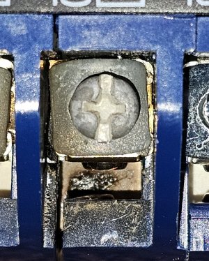
It does look as though it was (is) an internal defect in the switch. No reason for the "Line" contact to burned as that was making good contact. I know where you are coming from with respect to "Post-mortems" I always want to take things apart and find out what went wrong and why. However if you have a good look and cannot see anything obviously different in that contact assembly, compared to the others, I would put it down to a Chinese "Friday afternoon" job:unsure:
Just make sure that you have a good look at the new one when fitting and get all your connections good and solid. See my previous note about crimps or "U" turns in the tails. Good luck!🤞
 
Top