PaulRainbow
Well-Known Member
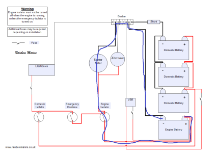
The negative arrange in my schematic is the same as the OPs, as is the positive arrangement, that is what he has said and it's the most common arrangement on the planet (for boats).It is the negative arrangement in this diagram that I think some have in mind rather than the earlier one. Ie a shared cable rather than parallel. 2 circuits sharing a common -ve wire. Certainly this is the arrangement on my boat (not the +ve side though - I am not talking about that).
To get a voltage drop you need a circuit, as there is no positive connection there is no circuit and a voltage drop on the domestic systems is impossible. A circuit consists of a positive and a negative connection. You cannot have current going from the domestic negative to the battery negative without the positives being connected, surely you know this ?So, what would you see in terms of voltage drop at both the individual loads if there was a poor connection in the 'to all negatives' line when you turn the engine over, assuming the +ve sides are separate? Would you see a voltage drop in both circuits? It's hard to see how you wouldn't as you can't have 2 potential differences for the same wire. If so, would it be more apparent when you turn the engine over and you put a big load down it?
As above, the OP states that the negatives are connected but the positives are separate circuits with their own isolator switches, therefore he has the same circuits as in the diagram i posted.Do we know what the -ve arrangement is for the OP - I cannot see it? How do you know it isn't this one as so many seem to?

