Instruments turn off when starting engine having added extra battery,

Andrew_Trayfoot

Active member
Joined
11 Oct 2007
Messages
648
Visit site
Doesn't need to warm up. Any current in any wire will cause a voltage drop (it is called Ohm's Law). In rush current in a starter motor is said to be about 8-10x the normal current so can easily be above 500A for a couple of seconds. That will cause a voltage drop of more than 1V for every metre of cable (with 16mm cable that is undersized).

It is always amusing people telling me it can't happen when I have seen it for myself :) In my case my GPS has reported a voltage of 9.6V when the engine is starting.
Interesting.
This one will run and run! :)
 

bedouin

Well-known member
Joined
16 May 2001
Messages
32,339
Visit site
where is this "inrush" current that is increasing the voltage on the negative side of the starter motor(the thing doing work) coming from? I'm afraid you need to draw a circuit diagram and show me where the positive voltage that is lifting the battery neg is being generated.
Google is your friend. There is nothing at all controversial with the idea of inrush current for starter motors (or any motor). I could try explaining about back EMF and stalled motors but if you don't even understand ohm's law it would go over your head. The instant power is applied to the starter motor there will be at most 6V across the motor itself - the rest is lost in the wiring and the internal resistance of the battery.

Whenever you draw a circuit diagram any wire should really be drawn as a resistor and you have to understand the voltage drop. Especially important in boats where you have long cable runs driven by 12V - it doesn't take much to get a 1V drop on a long cable run.

So any wire that is shared between the starting current and the supply to the instrument is acting as a resistor and so reducing the supply voltage as seen by the instrument.
 

Buck Turgidson

Well-known member
Joined
10 Apr 2012
Messages
3,188
Location
Zürich
Visit site
Google is your friend. There is nothing at all controversial with the idea of inrush current for starter motors (or any motor). I could try explaining about back EMF and stalled motors but if you don't even understand ohm's law it would go over your head. The instant power is applied to the starter motor there will be at most 6V across the motor itself - the rest is lost in the wiring and the internal resistance of the battery.

Whenever you draw a circuit diagram any wire should really be drawn as a resistor and you have to understand the voltage drop. Especially important in boats where you have long cable runs driven by 12V - it doesn't take much to get a 1V drop on a long cable run.

So any wire that is shared between the starting current and the supply to the instrument is acting as a resistor and so reducing the supply voltage as seen by the instrument.
sorry but you need to increase the voltage in the battery neg above zero for your theory to work. we are talking about a combined neg but not positive. There is no circuit. By your theory the earth voltage has been lifted above zero for everything connected to that earth so I guess the neighbouring boats should expect a voltage drop too!

Draw a picture and show me how the voltage in a separate circuit connected to the same earth changes due the starter motor operation.
 

billskip

Well-known member
Joined
6 Sep 2001
Messages
9,976
Visit site
Google is your friend. There is nothing at all controversial with the idea of inrush current for starter motors (or any motor). I could try explaining about back EMF and stalled motors but if you don't even understand ohm's law it would go over your head. The instant power is applied to the starter motor there will be at most 6V across the motor itself - the rest is lost in the wiring and the internal resistance of the battery.

Whenever you draw a circuit diagram any wire should really be drawn as a resistor and you have to understand the voltage drop. Especially important in boats where you have long cable runs driven by 12V - it doesn't take much to get a 1V drop on a long cable run.

So any wire that is shared between the starting current and the supply to the instrument is acting as a resistor and so reducing the supply voltage as seen by the instrument.
I think the term "potential difference" needs to be understood.
 

Iliade

Well-known member
Joined
27 Apr 2005
Messages
2,137
Location
Shoreham - up the river without a paddle.
www.airworks.co.uk
As intimated by others above, If they all share a common negative connection, try cleaning the mating surfaces of said terminals & connectors and make sure they are correctly tightened. If attempting to pull a high current through a poor connection you could increase the resistance at that connection and thereby influence the house system. i.e. Check the simplest things first.
 

PaulRainbow

Well-known member
Joined
16 May 2016
Messages
15,882
Location
Suffolk
Visit site
As intimated by others above, If they all share a common negative connection, try cleaning the mating surfaces of said terminals & connectors and make sure they are correctly tightened. If attempting to pull a high current through a poor connection you could increase the resistance at that connection and thereby influence the house system. i.e. Check the simplest things first.
Another one that doesn't understand, you cannot "influence" the house system by only having the negative connected, the positive must be connected too.
 
Last edited:

PaulRainbow

Well-known member
Joined
16 May 2016
Messages
15,882
Location
Suffolk
Visit site
Google is your friend. There is nothing at all controversial with the idea of inrush current for starter motors (or any motor). I could try explaining about back EMF and stalled motors but if you don't even understand ohm's law it would go over your head. The instant power is applied to the starter motor there will be at most 6V across the motor itself - the rest is lost in the wiring and the internal resistance of the battery.

Whenever you draw a circuit diagram any wire should really be drawn as a resistor and you have to understand the voltage drop. Especially important in boats where you have long cable runs driven by 12V - it doesn't take much to get a 1V drop on a long cable run.

So any wire that is shared between the starting current and the supply to the instrument is acting as a resistor and so reducing the supply voltage as seen by the instrument.
You have been reading too much on Google and have not fully understood what you have read.

Connecting the negatives from both systems does not make it possible to create a voltage drop from one circuit to another. Unless the positives are both connected, it just is not possible.

You say that your instruments are affected by starting the engine, in which case you must have both a negative and a positive connection between both systems.
 
Last edited:

Refueler

Well-known member
Joined
13 Sep 2008
Messages
17,805
Location
Far away from hooray henrys
Visit site
where is this "inrush" current that is increasing the voltage on the negative side of the starter motor(the thing doing work) coming from? I'm afraid you need to draw a circuit diagram and show me where the positive voltage that is lifting the battery neg is being generated.

As they say - You cannot get anything from nothing ....
 

Refueler

Well-known member
Joined
13 Sep 2008
Messages
17,805
Location
Far away from hooray henrys
Visit site
Google is your friend. There is nothing at all controversial with the idea of inrush current for starter motors (or any motor). I could try explaining about back EMF and stalled motors but if you don't even understand ohm's law it would go over your head. The instant power is applied to the starter motor there will be at most 6V across the motor itself - the rest is lost in the wiring and the internal resistance of the battery.

Whenever you draw a circuit diagram any wire should really be drawn as a resistor and you have to understand the voltage drop. Especially important in boats where you have long cable runs driven by 12V - it doesn't take much to get a 1V drop on a long cable run.

So any wire that is shared between the starting current and the supply to the instrument is acting as a resistor and so reducing the supply voltage as seen by the instrument.

BUT - you are saying that the negative lead from domestic is suffering from that voltage drop / load - even though the domestic + is not connected in any way or form to that load ... as far as the domestic is concerned - its an OPEN non connected circuit to the starter ... QED !

Ohms law has nothing to do with sheer simple physical lack of +ve connection !!
 
Last edited:

PaulRainbow

Well-known member
Joined
16 May 2016
Messages
15,882
Location
Suffolk
Visit site
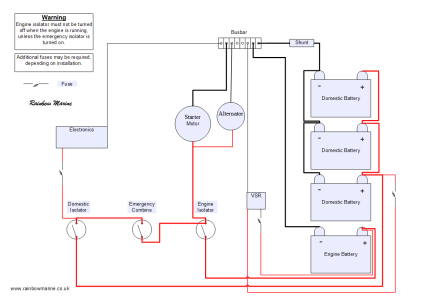
The OP has two separate circuits, one for the engine and one for the domestics.

They have a common negative, as do the vast majority of boats. This is typically so you can have an emergency parallel switch or for a battery monitor to correctly work, including taking into account the alternator charge going to the domestic batteries.

There is no connection between the positives of the two systems and they have separate isolators. The only time the OP will have a positive connection between the two systems is when the VSR is closed, creating a parallel connection between both systems. The OP has solar panels which could be creating enough charge to activate the VSR and and cause the batteries to be in parallel, hence the voltage drop on the domestic systems.

Without the positive connection it is absolutely 100% impossible to cause a voltage drop on one system by drawing any amount of current from the other system.

This is a typical system, similar to the OPs, you can clearly see there is no positive connection between the two banks unless the VSR is closed. :

Charging-2-banks-VSR.png
 

Refueler

Well-known member
Joined
13 Sep 2008
Messages
17,805
Location
Far away from hooray henrys
Visit site
The OP has two separate circuits, one for the engine and one for the domestics.

They have a common negative, as do the vast majority of boats. This is typically so you can have an emergency parallel switch or for a battery monitor to correctly work, including taking into account the alternator charge going to the domestic batteries.

There is no connection between the positives of the two systems and they have separate isolators. The only time the OP will have a positive connection between the two systems is when the VSR is closed, creating a parallel connection between both systems. The OP has solar panels which could be creating enough charge to activate the VSR and and cause the batteries to be in parallel, hence the voltage drop on the domestic systems.

Without the positive connection it is absolutely 100% impossible to cause a voltage drop on one system by drawing any amount of current from the other system.

This is a typical system, similar to the OPs, you can clearly see there is no positive connection between the two banks unless the VSR is closed. :

View attachment 174653

I know OP hasn't got the old 1-0-2-B switch - but basically same applies there ...

Even though -ve is common to all - the only time both circuits interact together is when switch is put to BOTH.
 

PaulRainbow

Well-known member
Joined
16 May 2016
Messages
15,882
Location
Suffolk
Visit site
I know OP hasn't got the old 1-0-2-B switch - but basically same applies there ...

Even though -ve is common to all - the only time both circuits interact together is when switch is put to BOTH.
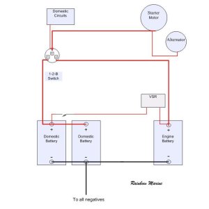
Sorry to disagree, but the normal setup for the 1-2-B switch is that the BOTH setting parallels the two batteries. The two circuits are both in parallel on settings 1 and 2

Charging 2 Batteries One Engine  VSR and 1-2-B.jpg
 

Momac

Well-known member
Joined
7 Feb 2008
Messages
6,706
Location
UK
Visit site
I get this same issue as my domestic bank starts the starboard engine while also powering the mfd.
I manage it by no switching the mfd on until after the engines are running.
It could be possible to connect both battery bank positives to the mfd through diodes which would then manage the voltage drop. I may try that one day.
 

PaulRainbow

Well-known member
Joined
16 May 2016
Messages
15,882
Location
Suffolk
Visit site
I get this same issue as my domestic bank starts the starboard engine while also powering the mfd.
I manage it by no switching the mfd on until after the engines are running.
It could be possible to connect both battery bank positives to the mfd through diodes which would then manage the voltage drop. I may try that one day.
Or you could move the starboard starter cables to the engine battery.

My Princess has a pair of engine batteries (in series for 24v) and a separate bank for the domestics. It did not have an emergency parallel switch, so a flat engine battery would leave us dead in the water, so i fitted one.

With your current arrangement you would have one engine if one battery failed, but could lose an engine and all electrics if the Stb one failed, unless you have an emergency parallel switch. Separate engine and domestic banks, with an emergency parallel switch solves both issues.
 

Momac

Well-known member
Joined
7 Feb 2008
Messages
6,706
Location
UK
Visit site
Or you could move the starboard starter cables to the engine battery.

Yes that would work .
Not really sure why it is not wired that way from new. .

There is an emergency link switch on a press and hold switch .

The diode solution would be relatively cheap. There is allegedly a diode pack on the boat specifically for this use but I have not found it . Presently the voltage drop is not a big issue so something I may sort out one day. I have a plan in place to create more time for tinkering with things , including the boat.
 
Top