An electrical puzzle..

youngkath

New member
Joined
12 Jun 2018
Messages
15
www.thesailingnomads.com
Hi there folks,

Firstly, we have gained a huge amount of information from historic threads in this forum. So to all the regular posters, who have helped us fix our stern gland, fridge, water pump(s), countless engine leaks etc. etc. THANK YOU.

However... as always the boat jobs continue, and this is one (after 2 years extra experience) we just can’t fathom... whyyyy?!

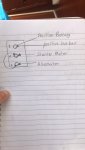
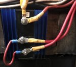
To jump to the punchline, just checkout the photos below.

Or if you’re into the detail, here’s the story...(!) We had just launched the boat for the first time, cruised slowly from Preveza to Nydri. Fitted was a VSR combiner, with a Blamar regulator and alternator.

Then our batteries gassed... egg smell galore, the lot. We pulled into Nydri and a British electrician, offered to hook us up with a spare... 5min job - brilliant...

However... he also told us that our batteries were not isolated and advised we removed the combiner for a split diode. He was not a fan of “gadgets” or “ready glossy magazines” which we now think means, electrical technology beyond 1970. In our naivety we let him go ahead and paid him.

We’ve limped along ever since, thankfully with our solar and wind generator in the Aegean keeping us going. Amazingly, we’ve only just realised that we don’t think the house batteries are being charged at all by the alternator... only the start.

Before we start taking it apart, can anyone fathom whyyyyyyyy?! Are we missing something and do any electrical experts have advice on best solution for our setup:

340ah batteries
295 watt solar
Aero6gen

Huge thank you for reading and your comments in advance :)

Kath & T
 

Attachments

  • A38FE5AE-1D2C-4DF9-A653-E918C357CF68.jpeg
    A38FE5AE-1D2C-4DF9-A653-E918C357CF68.jpeg
    318.1 KB · Views: 198
  • 3BAB8BC3-19E2-4ACD-8401-3020C94BA917.jpeg
    3BAB8BC3-19E2-4ACD-8401-3020C94BA917.jpeg
    91 KB · Views: 189

VicS

Well-known member
Joined
13 Jul 2002
Messages
48,255
Visit site
If your picture and diagram are of a diode splitter whoever wired it up should be keel hauled , not paid.

But how are the batteries and battery switching arranged

A dedicated engine start battery and a large house bank ?

Separate isolators with an emergency combining / crossover switch or a 1,2 both selector switch /
 

andsarkit

Well-known member
Joined
27 Aug 2015
Messages
1,177
Location
Dartmouth
Visit site
I suspect that the alternator/starter connection also connects to the starter battery via an isolating switch. Only one of the diodes is being used to charge the house batteries and the resulting voltage drop will stop them ever being fully charged although they will still receive some charge.
The initial gassing problem could have been caused by a faulty regulator or an internal battery fault. If the start battery is charging properly then the regulator is probably OK.
If the combiner was working properly the batteries are isolated unless being charged by the alternator.
The first thing you need to do is get hold of a multimeter and check voltages on the batteries at rest and also when charging. When you have some readings someone on here will be able to provide more useful advice.
It is always a good exercise to draw out your electrical system to assist with fault finding. A good job for a rainy day.
 

pvb

Well-known member
Joined
16 May 2001
Messages
45,604
Location
UK East Coast
Visit site
It's impossible to tell what's happening, except that you seem to have been conned, which you already know. There's no reason to remove a VSR and replace it with a diode splitter. You need to find someone sensible and knowledgeable to sort it out for you.
 

PaulRainbow

Well-known member
Joined
16 May 2016
Messages
15,923
Location
Suffolk
Visit site
The wiring on the diode is an absolute disgrace.

The link wire should not be there, remove it.

The wire from the alternator goes to the "A" terminal.

Terminal 1 goes to the positive of one bank, terminal 2 goes to the positive of the other bank.

Your diagram shows a cable going to the starter motor, if this goes to the main battery cable at the starter, that's OK, this will charge the engine battery. But, you must make certain that there is not a short cable from that starter terminal to the output of the alternator.

You show two cable going to terminal 1. There should be a single cable going to the domestic bank. You also show a cable going to the "positive busbar", this needs investigating. Did the moron who did the wiring add this wire ? If it is going to the positive busbar after the isolator switch, you cannot isolate the domestic circuits while the engine is running. I need to know exactly where this wire goes and if it was added as part of the diode installation.

PVB is correct, there was no need to swap the VSR, do you still have the VSR ?
 

TernVI

Well-known member
Joined
8 Jul 2020
Messages
5,070
Visit site
There was clearly something something badly wrong before the chap from Nydri got involved.
I would suggest reverting to a very basic system and checking everything.
The hydrogen sulphide smell suggests overheating. Either too high a charging voltage or a damaged cell.
This is a dangerous condition.
The gas is poisonous and you run the serious risk of an explosion.
The linking cable on the diode block is definitiely not normal. The only expanations for it that I can see are 1) the electrician had some strange ideas, 2) one diode is faulty 3) the current is too much for one diode 4) you might concievably put the link there temporarily while testing things,

There may be other things going on which you haven't showed us. We cannot safely assume the rest of the system is what we would hope/expect it to be.
Suggesting fixes to a boat we have not seen is fraught because there are many yachts out there with quite curious systems. To properly suggest a cure, I would want sight of the whole system.

Best thing to do is plenty of fresh air to clear away any gas, then isolate the batteries and go to the pub.
 

VicS

Well-known member
Joined
13 Jul 2002
Messages
48,255
Visit site
The wiring on the diode is an absolute disgrace.
The OP says he has a Balmar alternator and regulator

Am I right in thinking this is battery sensed ?
If so there should be a battery sensing connection from the regulator to the house battery terminal of the diode splitter. or the isolator switch. If this connection is missing it could explain the overcharging experienced.
 

PaulRainbow

Well-known member
Joined
16 May 2016
Messages
15,923
Location
Suffolk
Visit site
The OP says he has a Balmar alternator and regulator

Am I right in thinking this is battery sensed ?
If so there should be a battery sensing connection from the regulator to the house battery terminal of the diode splitter. or the isolator switch. If this connection is missing it could explain the overcharging experienced.

No mention of that in post #1 Vic, i take it you're getting that from another thread ?
 

prv

Well-known member
Joined
29 Nov 2009
Messages
37,363
Location
Southampton
Visit site
No mention of that in post #1 Vic, i take it you're getting that from another thread ?

Post 1 says "Blamar alternator", which is pretty obviously a typo for Balmar. I'm not familiar with their product range but my impression is of advanced high-output alternators which, like Vic, I'd expect to be battery-sensed.

You'd hope that a battery sense wire becoming completely disconnected would result in a fallback to machine-sensed, rather than overcharging (at least, that's what my Merlin booster does) but perhaps if the connection was intermittent or high-resistance it could mislead the regulator.

Pete
 

pawl

Member
Joined
30 Aug 2018
Messages
117
Location
Hampshire
Visit site
hi, as others have said, there is too little information to give any really useful advice. The photo seems to be the diode splitter which the electrician fitted ( I assume). This should have one input and two outputs. The charging cable from the alternator goes to the input and the two battery banks should be connected one to each of the outputs. You could use the starter motor to connect to the starter battery I suppose. The worrying item in your photo is the jumper cable between terminals 2 and A, that shouldn't be there, so you have to wonder whether the splitter actually works. Also you should make sure that the cables are attached to the correct terminals.

The drawback with the diode splitters over the VSR is the inherent voltage drop. You should have a sensor wire from the Balmar regulator to one of the battery banks, most likely the house bank. You should ensure that this is properly connected to the battery terminal. There should also be a temperature sensing wire to prevent the batteries overheating. I'm not familiar with the Balmar products so it's possible that they may have a different arrangement or even combined it with the voltage sensor.

In view of the previous overcharging problems you should check the actual charging voltage at the batteries once you have got the wiring sorted out.
 

PaulRainbow

Well-known member
Joined
16 May 2016
Messages
15,923
Location
Suffolk
Visit site
Post 1 says "Blamar alternator", which is pretty obviously a typo for Balmar. I'm not familiar with their product range but my impression is of advanced high-output alternators which, like Vic, I'd expect to be battery-sensed.

You'd hope that a battery sense wire becoming completely disconnected would result in a fallback to machine-sensed, rather than overcharging (at least, that's what my Merlin booster does) but perhaps if the connection was intermittent or high-resistance it could mislead the regulator.

Pete

Looks like a trip to Specsavers for me :mad:
 

VicS

Well-known member
Joined
13 Jul 2002
Messages
48,255
Visit site
Post 1 says "Blamar alternator", which is pretty obviously a typo for Balmar. I'm not familiar with their product range but my impression is of advanced high-output alternators which, like Vic, I'd expect to be battery-sensed.
You'd hope that a battery sense wire becoming completely disconnected would result in a fallback to machine-sensed, rather than overcharging (at least, that's what my Merlin booster does) but perhaps if the connection was intermittent or high-resistance it could mislead the regulator.

Pete
I've taken another look at the manual.... It says that the regulator will not wok if the sense wire is not connected ... but in what way it wont work is not stated
If the sense wire is connected to a battery which is not being charged ( the OPs say that they think the house battery is not being charged by the alternator ) it would probably explain the overcharging of the other one .... Maybe ???

Its all speculation though .
 

youngkath

New member
Joined
12 Jun 2018
Messages
15
www.thesailingnomads.com
Hi folks,

Firstly, a huge thank you for your input and thoughts. Whilst we fully appreciate you can’t completely diagnose and recommend safe next actions, your thoughts and questions are extremely helpful in furthering our enquiries!

To clarify some of your questions (the ones we can answer!):

1. The gassing happened before the Nydri electrician worked his “magic”..
2. The Alternator is a Balmar 6-series and the regulator is a Balmar ARS-4
3. The red voltage sense wire from the regulator is connected to the alternator positive output
4. The alternator positive output is connected to position ‘1’(!!!!) on the diode splitter and the position ‘A’ of the diode splitter is connected to the starter motor
5. The electrician removed our combiner and installed a simple ‘on’, ‘off’ isolation switch to the negative cable of the battery
6. We are 99% sure the house bank is not being charged by the alternator, but we will perform the multimeter test suggested
7. Yes we still have the VSR, so reinstalling might be good idea.... to avoid the voltage drop, as well as having the emergency house bank to start option seems sensible
8. The two cables to position ‘2’.... so one leads to the positive busbar of the instrument panel and the other to the positive terminal of battery.. my hunch is that this cable was cut by our electrician in half and just joined at the splitter...

When we had the work done in Nydri, we had literally only just bought the boat, launched her and had the gassing problem approx two weeks in. The electrician was hired in the hope we could save the season and postpone the electrical learning for at least a few months...we’ve learnt a LOT now, not to mention a degree in how to work with contractors! Our intention still is and has always been to be totally independent and able to fix everything on the boat. We are two years in and getting closer and closer... electrics is our weak spot.

Many thanks again for all your input, we are in the deep Mani, so signal is varied, but I will keep you updated as best I can.

All the best,
Kath (yes a girl ;)) and T (also a girl!)
 
Last edited:

pawl

Member
Joined
30 Aug 2018
Messages
117
Location
Hampshire
Visit site
Hi folks,

Firstly, a huge thank you for your input and thoughts. Whilst we fully appreciate you can’t completely diagnose and recommend safe next actions, your thoughts and questions are extremely helpful in furthering our enquiries!

To clarify some of your questions (the ones we can answer!):

1. The gassing happened before the Nydri electrician worked his “magic”..
2. The Alternator is a Balmar 6-series and the regulator is a Balmar ARS-4
3. The red voltage sense wire from the regulator is connected to the alternator positive output
4. The alternator positive output is connected to position ‘1’(!!!!) on the diode splitter and the position ‘A’ of the diode splitter is connected to the starter motor
5. The electrician removed our combiner and installed a simple ‘on’, ‘off’ isolation switch to the negative cable of the battery
6. We are 99% sure the house bank is not being charged by the alternator, but we will perform the multimeter test suggested
7. Yes we still have the VSR, so reinstalling might be good idea.... to avoid the voltage drop, as well as having the emergency house bank to start option seems sensible
8. The two cables to position ‘2’.... so one leads to the positive busbar of the instrument panel and the other to the positive terminal of battery.. my hunch is that this cable was cut by our electrician in half and just joined at the splitter...

When we had the work done in Nydri, we had literally only just bought the boat, launched her and had the gassing problem approx two weeks in. The electrician was hired in the hope we could save the season and postpone the electrical learning for at least a few months...we’ve learnt a LOT now, not to mention a degree in how to work with contractors! Our intention still is and has always been to be totally independent and able to fix everything on the boat. We are two years in and getting closer and closer... electrics is our weak spot.

Many thanks again for all your input, we are in the deep Mani, so signal is varied, but I will keep you updated as best I can.

All the best,
Kath (yes a girl ;)) and T (also a girl!)
hi, you can overcome the voltage drop problem by moving the regulator sense wire from the alternator to the positive battery terminal. It would be much better connected that way in any case. There may be an in-line fuse somewhere in the cable, worth checking that this is ok.

You might also check that the regulator settings are correct for your battery type e.g. Wet flooded cell lead/acid, Sealed maintenance free or other. However, if your house and starter batteries are different technologies then you will have to arrange things differently.

I would be concerned about the work carried out at Nydri as I can't see how the VSR could cause the overcharging, it's simply a switch. The diode splitter wiring looks to be incorrect. Assuming, I don't like making assumptions, but assuming that the terminal identification is as your sketch then I would have thought that the alternator output should go to the terminal marked "A" the wire to the starter should be on either "1" or "2" and the house batteries on the remaining terminal. Any "jumper" wires connecting any of the terminals together completely defeats the point of having the unit which is why I suggested, in my previous post that this unit may not actually work.

As the splitter is wired at the moment if it is working it would charge the starter battery ok but because of the voltage drop it would only provide a minimal charge to the house batteries. If it is not working it would still charge the starter battery because of the "jumper" wire but would not charge the house batteries at all.

Both battery banks really should have isolation switches on the positive side. I think that you would be better off getting the basic wiring sorted out and then, if there is still an overcharging problem, sort that out.

I hope this helps.
 

VicS

Well-known member
Joined
13 Jul 2002
Messages
48,255
Visit site
Hi folks,
>
Many thanks again for all your input, we are in the deep Mani, so signal is varied, but I will keep you updated as best I can.

All the best,
Kath (yes a girl ;)) and T (also a girl!)

Hi Girls

Here are a couple of diagrams which may help to distinguish between the wiring required for a VSR and that required for a diode splitter
It seems logical that the alternator should connect to "A" and the batteries to "1" and "2" on the diode splitter but it would be sensible to check with the installation instructions.

It is important that the sense wire has a good connection to wherever it has to go. A bad connection will lead to over charging.

DSCF1797.jpg
DSCF1798.jpg
 
Top