New build Sanlorenzo SL96A 2024

Chiara’s slave

Well-known member
Joined
14 Apr 2022
Messages
6,128
Location
Western Solent
Visit site
I'd be curious to hear which situation you have in mind, because imho having domestic water completely disconnected from the engines is always the best choice, from a technical viewpoint.
I fully appreciate that in a smallish boat mostly used without running the genset (or with no genset at all), warming domestic water with the engine(s) can be necessary.
But that isn't a matter of good vs. bad choices, it's just a necessary evil triggered by lack of alternatives!
I’m referring to the choice to circulate the hot water, not how you make it hot. I accept your point re calorifiers.
 

Portofino

Well-known member
Joined
10 Apr 2011
Messages
12,175
Location
Boat- Western Med
Visit site
Yep, we already debated this. And yep, indeed there are engine take offs in your MANs (as well as in mine, which are bigger).
They just happen to be disconnected from the heater - which might be an original Amati's choice, and if it was, I agree with it.
But they could also have been disconnected by some previous owner, as I did on my boat, unless you know better.
Ref. the MTU monsters in jfm's SL, I can't be positive, but I'd be slightly surprised if they wouldn't have (plugged) in-out connections somewhere along their closed cooling circuit.
That has nothing to see with the fact that they will never be used, for several good reasons - none of which are related to engines sensors, anyway.
If that would be the case, why would MAN continue to provide take offs also in their latest common rail engines, which rely on all sort of electronic gizmos?

Last but not least, ref. boat seriousness, I'm glad you appreciated my indirect compliment, but don't get too excited.
There's plenty of other much more important boxes that in my books should be ticked, to qualify a serious boat.
Like for instance being able to drop the anchor in an emergency without risking a crew member life, just to name a very basic must-have.
Does the Viking 92 (no less!) with a laughable flush deck recently beached in FL ring a bell? :ROFLMAO:
Thx for the polite reply P .
The hand book ( full of schematics) show no take off .Never was any .
I did say “ MASSIVE “ in terms of Water vol flow . Read into that context wise what you will ?

Modern German engines do not only have temp parameters but time to each certain points in the range after a start up .
As said all behind the scenes , but something a lap topped tech might pick up .No biggie .You have dig deep .

Anyhow it’s all rather academic as the hot water in this SL isn’t reliant on the main propulsion engines just like my boat was built …….suspect many more marques .Nothing remarkable there in my book .
 

MapisM

Well-known member
Joined
11 Mar 2002
Messages
20,345
Visit site
I’m referring to the choice to circulate the hot water, not how you make it hot. I accept your point re calorifiers.
Ops, sorry for misunderstanding your point.
Though I must say that I struggle to think also of a reason/situation where circulation could be a bad choice.
In fact, also in my much smaller (56') boat, there isn't a hot water circulation pipe, but (particularly when living aboard in wintertime), I would definitely appreciate it - not to mention SWMBO, who I'm sure would love it!
 

MapisM

Well-known member
Joined
11 Mar 2002
Messages
20,345
Visit site
The hand book (full of schematics) show no take off. Never was any.
It's nowhere to be found also in the schematics of my V8s manuals, but it's definitely there in flesh.
And as I believe to have mentioned in the other thread where we already discussed this, I've seen it also in another R6 powered boat.
Which btw has common rail engines, hence newer than yours.
It beggars belief that there was no take off in your block, and they added it in the very same block afterwards.
If anything, calorifiers take offs were much more popular in older rather than newer boats/engines...
 

Portofino

Well-known member
Joined
10 Apr 2011
Messages
12,175
Location
Boat- Western Med
Visit site
It's nowhere to be found also in the schematics of my V8s manuals, but it's definitely there in flesh.
And as I believe to have mentioned in the other thread where we already discussed this, I've seen it also in another R6 powered boat.
Which btw has common rail engines, hence newer than yours.
It beggars belief that there was no take off in your block, and they added it in the very same block afterwards.
If anything, calorifiers take offs were much more popular in older rather than newer boats/engines...
Sorry I was referring to the boat manual that came with the boat .No take off from the engines .The engine manuals only show parts diagrams and basic servicing / fault funding charts .Schematics are only found in the boat builder manuals and plans , wiring plans , plumbing plans , fire fighting , bilge pump etc etc , inc H + C Water supply.

But the supply circuit from an engine if any wouldn’t be MASSIVE anyhow .So doable especially with ancient electrotwackery by todays stds .But Amati didn’t do it . You wouldn’t run into different rate of heat build up issues with a todays R6 in a 50 fter heating a normal tank for 3 cabins , because it’s not a MASSIVE circuit .

I haven’t seen any obvious take off nipples on either engine .Where are they on the R6 ?
Block is a marinised version of the D28 evolution used mostly for on road and rail applications.
So maybe boat builders had to request take off from MAN ….connected to the marinised bits to one side ? ie not std fitting .Dunno who cares ? Boats never had them .

Just out of interest does both your engines have take off nipples for the hot water or only one on the tank side ?
Volvo KADs did if my memory serves , only the starboard one …..which means slightly different kit bolted on the blocks .

So not inconceivable to specc a pair without .” take offs “ In other words you have to opt in .

I very much doubt MTU with JFM s boat size do a hot water take off kit .One more thing to go wrong in a show stopper way bleeding coolant away into a leaky HE in the hot tank out of sight .Think of the sequel of contaminating engine coolant into the boats hot water supply. First principles dictates don‘t mix if there’s a better alternative.

Hot water on my boat is generated exactly like JFM s but sans the circulation pump as the faucets for obvious reasons are sufficiently close to the tank for a short warm up time .But I do get it for bigger boats .Neat touch .Suspect the plus sized Sunseeker/ Princess have this circulation system too? Same issues .

We have a inverter too for the small element in a small hot tank , but never used it on its own ,not necessary in the Med summer because I am conscious of its batt sapping potential. I may have played with it switched on while the engines were running and kept an eye on the batt gauges but nothing remarkable happened other than the hot water got hotter es expected .

Never ran out of hot water FWIW .Use the geny often enough @ anchor to supply 220v .
So we have alternative to a colorifer .

1-220 v shore power
2-220 v geny
3- inverter

Also RINA certified FWIW .
 

MapisM

Well-known member
Joined
11 Mar 2002
Messages
20,345
Visit site
So not inconceivable to specc a pair without .” take offs “ In other words you have to opt in .
It is inconceivable, because the two holes are in the engine block casting.
You want to use them, you just unscrew the plugs. You don't, you live them in place. It's that simple.
I suggest we are done to death with this storm in a teacup!
 

jfm

Well-known member
Joined
16 May 2001
Messages
23,698
Location
Jersey/Antibes
Visit site
Hot water on my boat is generated exactly like JFM s but sans the circulation pump as the faucets for obvious reasons are sufficiently close to the tank for a short warm up time .But I do get it for bigger boats .Neat touch .Suspect the plus sized Sunseeker/ Princess have this circulation system too? Same issues .
FWIW sunseeker fit circ pumps (230v of course) as standard while Princess don't list it on their detailed spec sheet for X/Y 95. Probably they would if you asked. Princess Y95 has 200 litres hot water in one tank, whereas my project has 300 litres in 2x 150 tanks, each with 2x heating elements, so plenty of redundancy.

But the bigger plumbing spec difference is in the piping: Princess/Sunseeker are Hep2O type, not swaged fittings. And on the black piping side Sanlorenzo use thick walled solid drain piping with only short tails of flex pipe for the last metre at the WC end, whereas Prin/Seek use flexi hose all the way. I don't know about Sunseeker but Princess use T series diaphragm pumps to empty the X95 black tank, with one back-up pump, not proper Gianneschi-type mains voltage auger pumps with multiple back ups.
 

jakew009

Well-known member
Joined
29 May 2012
Messages
380
Visit site
@jfm I think I asked this question before but it might have been missed. Do SL have a complete 3D CAD model of the boat, down to every pipe and valve etc? Or do they just model the main structures and then have 2D drawings for all the electro mechanical stuff? Are say the cabinet hinges modelled accurately in the overall model?

And likewise, when they do a customised version like yours, do they modify the CAD model to accurately represent your boat before building it?

I spend a lot of time in CAD software at work, and it's always a tradeoff how much time you spend on making accurate CAD modes for a 1 off. I can't begin to imagine the effort in accurately modelling all the complex systems in this boat, but equally I can't imagine trying to put it all together without modelling it first to see if it would fit..!
 

jfm

Well-known member
Joined
16 May 2001
Messages
23,698
Location
Jersey/Antibes
Visit site
@jfm I think I asked this question before but it might have been missed. Do SL have a complete 3D CAD model of the boat, down to every pipe and valve etc? Or do they just model the main structures and then have 2D drawings for all the electro mechanical stuff? Are say the cabinet hinges modelled accurately in the overall model?

And likewise, when they do a customised version like yours, do they modify the CAD model to accurately represent your boat before building it?

I spend a lot of time in CAD software at work, and it's always a tradeoff how much time you spend on making accurate CAD modes for a 1 off. I can't begin to imagine the effort in accurately modelling all the complex systems in this boat, but equally I can't imagine trying to put it all together without modelling it first to see if it would fit..!
Hi Jake
Basically it is all 3D modelled.

Obviously the grp components are made from mould tools built off plugs cut by multi axis millers/cutters.

The interior furniture is all 3D. I have specified fabrics and furniture from 3rd party manufacturers and of course Sanlorenzo download their 3D models and fit them into the boat and incorporate them in renders. The interior render below is done from 3D models of fabrics, furniture, wood floor, etc.

Also Sanlorenzo make a lot of custom furniture which is all 3D, and this makes for perfect joints of course, plus it has allowed eg to check hinge locus for all the doors that I have specified “slats” on, which obvs makes them thicker. The kitchen is all 3D and eg built to accept a Samsung family hub fridge, which Sanlorenzo have never fitted before and which they didn’t have until after they built the kitchen.

The only part of your Q that I don’t know the answer to is piping/wiring. This might not be 3D, due to it not being worth it. I don’t know. Plumbing is mostly standardised and apart from choice of taps and some extra ventilation/extraction/recirc I couldn’t see any need to change the standard spec. Wiring is mostly bespoke because customer choice of appliances is bespoke. So I suspect all very 2D.

I’ll post some 3D screen shots later (no time now).
 

John100156

Well-known member
Joined
31 Oct 2007
Messages
2,618
Location
SANT CARLES DE LA RAPITA
Visit site
Yup on this hot water thing, as many have said this is a loop of constantly circulating hot water that repeatedly leaves the hot water tank, goes around the loop, and returns to the tank. Therefore hot water is available instantly at any tap, no matter how far from the tank....
I agree with JFM: On a boat of this size I would certainly opt for a dynamic DHWS flow and return system, the annual losses through well insulated pipework and energy consumed by a small circulator in the Med using this system is minimal, even if left running at night, the circulation pipework is kept at a constant temperature at all times (avoiding lengthy pipe heat-losses every time a single outlet is used at the distal end where this is not the case).

The reduction in dead-leg lengths means almost immediate HW flow at all outlets - great, particularly when showering!

Another minor benefit is reduced risk of legionella, you can even select a sensible elevated circulating temperature regime for short periods at night to mitigate further this risk. On smaller boats of course where the dead-legs are relatively short, its less of an issue of course, we always treat our stored water to avoid any bugs!
 

jfm

Well-known member
Joined
16 May 2001
Messages
23,698
Location
Jersey/Antibes
Visit site
John I agree every word of that but there is a further dimension to the energy side of things, that maybe I didn't explain above.

This boat has spot zero water, which is two water makers in series. The first one "WM1" is high pressure and desalinates seawater; the second one "WM2" purifies it further down to 2ppm. Both are reverse osmosis, not just filters or ion-exchange things.

When on the dock with a shore hosepipe, that water enters the system half way through the series and passes through WM2 only. So the boat's water tanks always have <2ppm water, whether that water came from the sea or the dock. This allows washdown on arrival in port in the evening with no need to squeegee, and it avoids crud build up in laundry equipment and dishwashers. It is also VERY nice to shower in.

So back to the HW circulation loop. Yes I lose a bit of energy from say 16 hours a day of pumping a tiny pump. And I lose some heat despite insulation, but its not much because the temp differential in med summer is perhaps 25 degrees C. But the energy saving from not having to run the big motors in WM1+2, or even WM2 alone, to replace the thousands of litres of lost "dead leg" water, far outweighs that energy loss. So i think it is a win win.

BTW, there is also a back up desalinator WM3 but that's not relevant to this post :)
 

rwoofer

Active member
Joined
1 Apr 2003
Messages
3,355
Location
Surrey
Visit site
Simply marvellous. WIth all that engineering and craftmanship it is very easy to see why big boats cost what they do. SL offering what I would call real value for money.

Often not the case - I cycle a lot and it is very hard to see how good race bikes can justify the £15k they now cost. Shockingly you can often build a bike from parts for less than the complete bike from the manufacturer - madness and poor value for money.
 

jakew009

Well-known member
Joined
29 May 2012
Messages
380
Visit site
Hi Jake
Basically it is all 3D modelled.

Obviously the grp components are made from mould tools built off plugs cut by multi axis millers/cutters.

The interior furniture is all 3D. I have specified fabrics and furniture from 3rd party manufacturers and of course Sanlorenzo download their 3D models and fit them into the boat and incorporate them in renders. The interior render below is done from 3D models of fabrics, furniture, wood floor, etc.

Also Sanlorenzo make a lot of custom furniture which is all 3D, and this makes for perfect joints of course, plus it has allowed eg to check hinge locus for all the doors that I have specified “slats” on, which obvs makes them thicker. The kitchen is all 3D and eg built to accept a Samsung family hub fridge, which Sanlorenzo have never fitted before and which they didn’t have until after they built the kitchen.

The only part of your Q that I don’t know the answer to is piping/wiring. This might not be 3D, due to it not being worth it. I don’t know. Plumbing is mostly standardised and apart from choice of taps and some extra ventilation/extraction/recirc I couldn’t see any need to change the standard spec. Wiring is mostly bespoke because customer choice of appliances is bespoke. So I suspect all very 2D.

I’ll post some 3D screen shots later (no time now).

Thanks for taking the time to explain. That's about what I thought it would be. I can relate to how useful having an accurate 3D model is for checking how everything fits together. It completely changes the new product development process (for the better).

Manufacturers are also getting much better at providing 3D models to 3rd parties to incorporate in their own designs.

My experience is that 3D modelling wiring looms is incredibly time consuming, and even though there are programs that can theoretically go from a 2D wiring diagram to a 3D harness, it's an utter pain in the ass and no one bothers. Plumbing might be slightly easier if it's mainly solid lengths.
 

jfm

Well-known member
Joined
16 May 2001
Messages
23,698
Location
Jersey/Antibes
Visit site
@jakew009 and anyone else who knows 3D modelling, here are a couple of examples. Would be grateful for any insights on this whole CAD design process. BTW a long time ago I did my degree in Mech Eng and worked as an engineer for a year, but that was right at the end of the 80s so it was before CAD arrived on the scene in 2D let alone 3D - I missed al that by less than 10 years and literally did hours of drawing using an actual pencil. In a nerdy way I find this whole process (3D modelling) fascinating so would be grateful for any thoughts/observations/lessons you can give

I have zillions of drawings like the one below, which is the base of the fly helm and co pilot seats. This is a fresh custom drawing for my boat, not off-the-shelf, It it 2D or 3D? The chairs are Besenzoni catalogue items so I guess Sanlorenzo have taken a 2D or 3D model of the chair provided by Besenzoni, and incorporated it into their drawing/model of the base (?)

fly-helm-seat-base-drawing.jpg


Next below are some others - these look definitely taken from 3D models - correct? In the first picture, the blue screens are I guess 3D models from Garmin and the green screens/throttle heads are 3D models from MTU, and sanlorenzo have combined these into their own model of the pilothouse, correct? And the last picture below is to show different positions to place the tender (which normally goes inside the garage by the way) and seems to have a 3D model of the 435 williams, incorporated into Sanlorenzo's 3D model of the boat. Is that how it all works?

Dash-Pilothouse-render-2.jpg

Dash-Pilothouse-render-3.jpg

Tender-on-platform.jpg
 
Last edited:

jfm

Well-known member
Joined
16 May 2001
Messages
23,698
Location
Jersey/Antibes
Visit site
My experience is that 3D modelling wiring looms is incredibly time consuming, and even though there are programs that can theoretically go from a 2D wiring diagram to a 3D harness, it's an utter pain in the ass and no one bothers.
Of course you would 3D model a wiring harness if making cars, but I can totally see the sense in your comment that it isn't worth it with boats. The successful manufacturers of big boats don't do it, and there is just one obvious outlier in boatbuilding which is Princess. They make click-together looms off the boat, like you find in cars, and I guess they do this through 3D modelling. I have often looked at this (for over a decade, and commented on here) and thought Princess have got these things badly wrong - in fact I feel 100% sure they have got this wrong. Not criticising the actual boats one bit, just the decisions by their management over the last decade of which overdone manufacturing of wiring harnesses is but one example.
 

jakew009

Well-known member
Joined
29 May 2012
Messages
380
Visit site
@jfm typically what now happens is the initial model is drawn as a 3D object built from a 2D sketch.

It's easier if I explain with some photos...

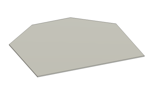
We start off with a sketch that may look something like this:
Screenshot 2024-01-04 at 11.03.05.png

Then it gets 'extruded' to make it a 3D object (or in this case turned into a piece of sheet metal):
Screenshot 2024-01-04 at 11.03.45.png

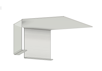
Then some flanges are added:
Screenshot 2024-01-04 at 11.05.07.png

Then some sketches may be drawn on other faces (in this case to add some holes:
Screenshot 2024-01-04 at 11.06.37.png

And then those sketched holes can be extruded through the 3D model:
Screenshot 2024-01-04 at 11.07.28.png

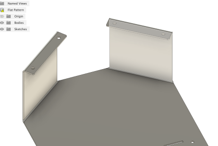
And finally some pemnuts might be inserted into the holes to give us threaded inserts. The models of the pemnuts are downloaded from the manufacturers website (you can see the instances of them on the left hand side):
Screenshot 2024-01-04 at 11.08.24.png

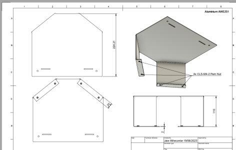
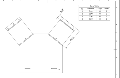
From this 3D model we can then generate a 2D manufacturing drawing which will be used on the shop floor:
Screenshot 2024-01-04 at 11.10.24.png

And the software can also generate the 'flat' pattern automatically. This shape can be lasered out of a piece of sheet metal and then press braked into the correct shape. The software calculates all the K factors to allow for the material deforming during bending:
Screenshot 2024-01-04 at 11.11.13.png

If you go back to the 3D model and change anything on it, the 2D drawings will automatically update. So effectively the 3D model is the 'master'. It's known as parametric CAD.

And then we can take this individual sheet metal component, and incorporate it into a higher level assembly. Here you can see a bunch of components that have been provided by the manufacturers (IR floodlights, latches from Metrol / Southco etc. Some manufacturers are weirdly protective over their CAD drawings and it's just quicker to model it yourself. The cameras in this example would take about an hour to model. There are also websites like Grabcad and TraceParts where you can sometimes find the STEP files you are looking for.
Screenshot 2024-01-04 at 11.13.36.png

You can go down to an extreme level of detail, modelling every nut and bolt etc. It massively speeds up the development process because it's much quicker for example to try different length bolts on a computer screen than it is in real life. You can also see how things fit together so much easier by being able to position them in space and then build mounting brackets etc around them. You can also then generate the BOMs (down to every last nut and bolt) and link all that to whatever ERP / PLM (product lifecycle management) type software you are using. One of the most tricky things is tracking the revisions of things you manufacture and then being able to supply spare parts to a customer a couple of years down the line when you've moved on a few revisions. Having accurate CAD models makes it a walk in the park.
Screenshot 2024-01-04 at 11.20.03.png

You can then incorporate these detailed models into even more complex assemblies:
Screenshot 2024-01-04 at 11.30.37.png

Which themselves will obviously comprise of many different sub assemblies
Screenshot 2024-01-04 at 11.31.37.png


In your photos it looks as if they have a very complex model that they have 'simplified' whilst they are only working on some parts of it. When the model gets enormous it starts to become slow to work with because there are so many individual components. I imagine there is 10s of man years of work to model a yacht like that.

I should say I have absolutely no engineering (or other) qualifications, so take all this with a pinch of salt :)
 
Last edited:

jakew009

Well-known member
Joined
29 May 2012
Messages
380
Visit site
Of course you would 3D model a wiring harness if making cars, but I can totally see the sense in your comment that it isn't worth it with boats. The successful manufacturers of big boats don't do it, and there is just one obvious outlier in boatbuilding which is Princess. They make click-together looms off the boat, like you find in cars, and I guess they do this through 3D modelling. I have often looked at this (for over a decade, and commented on here) and thought Princess have got these things badly wrong - in fact I feel 100% sure they have got this wrong. Not criticising the actual boats one bit, just the decisions by their management over the last decade of which overdone manufacturing of wiring harnesses is but one example.

The challenge with wiring diagrams is that unlike mechanical CAD, you really have to start with 2D diagrams and convert it to 3D.

The way PCBs are designed is your start off with a schematic something like this (which shows the high level blocks)
Screenshot 2024-01-04 at 11.40.13.png

And then at lower level (in this example PCIe -> USB3):
Screenshot 2024-01-04 at 11.41.13.png

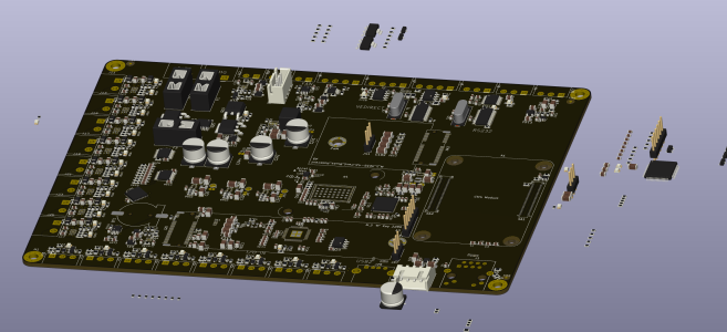
And from that it generates something like this. Every single little line is a 'wire' that you have to carefully route without it getting in the way of another wire. It's bad enough on a PCB where really the wires only go in two directions. I can't imagine trying to do it on a 100ft yacht :D
Screenshot 2024-01-04 at 11.42.14.png

And finally it can generate a 3D model which you could import into your mechanical CAD software:
Screenshot 2024-01-04 at 11.43.45.png

With regard to 'connectorising' the wiring harnesses, I would suggest there are plusses and minuses to it. It works best for volume production where you do the same thing over and over again. There are wire processing machines that can literally take wire off a spool, cut it to length, label it, strip it and crimp a terminal on either end in a matter of seconds. That's a far more scalable and reliable process than requiring an expensive marine electrician to lie on his back under a boat manually crimping connectors one at a time with a hand tool. Connectorising the harness also makes it much easier to test (because you can pre test all the harnesses before they are installed) and you can be certain the wiring diagram matches reality.

The downside (and I guess what you are alluding to) is that it makes it much more difficult to customise stuff on the production line, because you either have to start hacking up your beautiful looms, or you have to go through all the hassle of designing, documenting and finally manufacturing a loom that may only be needed once. Therefore you end up naturally rejecting even simple customisation request.
It also becomes difficult to 'swap out' components, because let's say you use a fan and the fan is supplied by the manufacturer with a custom connector on it that matches your harness. If a customer wants a different fan, you then have to get that manufacturer to put the custom connector on it or manually do it yourself which is a pita for a one off.

One thing that is nice with a connectorised wiring loom is that disassembling stuff is so much easier. If the flybridge helm is all connected with waterproof Deutsch DT connectors, you could remove it in a few seconds without a worry. If connectors haven't been used, you end up cutting wires and then joining them back together which is horrible. You could obviously connectorise a 'built in place' harness at sensible points, but few boat manufacturers seem to bother.

And then obviously the first thing a typical marine electrician is going to do as soon as he gets his hands on it will be to chop the pre installed connector off and no doubt use some sticky tape to extend :)
 
Top