New build Sanlorenzo SL96A 2024

MapisM

Well-known member
Joined
11 Mar 2002
Messages
20,360
Visit site
Their purpose is only to clean the water flow as it shoots out the back, so as not to hit the (big) swim platform so hard.
Makes perfect sense to me. (y)
And also explains why the plates are only on the inner sides of the tunnels, which is where the props push water not only backward, but also upward - as opposed to the external sides, where the thrust flow tends to be pushed "deeper" in the water.

But in your boots I wouldn't bother updating that YF thread with your explanation, for two reasons.
First, I'm sure some armchair genius would still raise endless objections.
And second - connected to first - life's way too short.
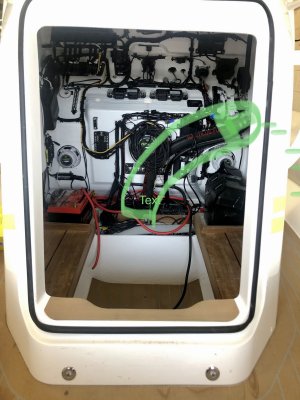
 :ROFLMAO:
 

Portofino

Well-known member
Joined
10 Apr 2011
Messages
12,210
Location
Boat- Western Med
Visit site
1+2 responses on my post 518 are from experts in hydrodynamics .Makes perfect sense.

Personally my take on interceptor plates on prop tunnels ( defined by very short L of 5- 15 mm intrusion ) is they are a neat way of harnessing otherwise lost energy .I see them an attribute .Something clever .

They haven’t put it on primarily to keep the underside of the bathing platform dry .They do smooth out the flow , but also create that back pressure in the tunnel direction as explained by 1-2 .
Otherwise why are they not fitted as std on every boat with or without tunnels + bathing platforms, if it’s that good so to speak ?

All naval naval architecture books agree prop tunnels on planing boats increase stern suction .That’s old hat .

let’s leave it here , it up to readers to figure out the advantages + disadvantages tunnels and how to mitigate these .

Reiterating my view on this fwiw ? = neat solution by SL .Nice touch of detail .

I did notice them earlier on the pics but in the interest of avoiding a row ( and accused of derailing ) thought best to keep schtum .How ever sap-2000 opened the stable door first .
 

PowerYachtBlog

Well-known member
Joined
21 May 2007
Messages
4,211
Location
Malta - Med Sea
www.poweryachtblog.com
In reality tunnels where designed to create cleaner propeller flow (losing less power) and better lift at speeds of 20 knots or more.
Levi debuted the first tunnels an addition to his surface drives on the Italcraft Drago where they worked as rudders, and I think then Hargrave used it in the first Hatteras hulls late seventies.
Hargrave system of hull integrated tunnels, is the one everyone started using, especially the British builders (FrPrSs and AzCr).
Porto is right as he is incorrect, in that tunnels can harm boat lift but at the lower end of speeds sub twenty knots.
It is possible that the harm we see in some production boats with tunnels too much bow high running, and high tens planning speeds is not for the tunnels alone.
It can be also because a hull was not designed for the tunnels, or the engines in that position. I made an hour discussing this with one of the Italcraft eng some years ago.
For example Ferretti experimented with tunnels in the early nineties, and they did not use for the reason that with aft located engines there hull was not working good.
The CFD analysis was good (I was told consulted by Buzzi btw), but when it came to real world on the 175 and 165 they abandoned tunnels for the two reasons I said above; bow high and planning speed from 12 to about 17/18 knots. They used tunnels for the first time when they launched the Ferretti 70 in 1996 which had central located engines.

Tunnels reduce that vertical energy waste, which as part of the waste helps the boat lift up at lower speeds and also lifting the bow which lifts the stern.
A late nineties Sunseeker 44 Camargue had this problem of lift bow high ride, not because the idea of putting V-drives with tunnels is wrong, it had this problem because it had a hull which was born in 1990 for the Camargue 46 and over the years had received very little modification. The lift problem was solved when they added the stern box after the first few hulls, the bow high problem remained.
The Camargue 44 replaced the 47 which had a very clean ride and nice angle at cruise, and much cleaner water.

But there is a note from this and all above that I just said, that propeller technology is also improving, and no prop is designed for vertical energy.
In reality that propeller vertical energy is a waste and should not exist.
So probably we are arriving at age when at certain speeds with or without tunnels propellers the vertical energy help for boat lift is diminish.
 

Elessar

Well-known member
Joined
10 Jul 2003
Messages
9,970
Location
River Hamble
Visit site
1+2 responses on my post 518 are from experts in hydrodynamics .Makes perfect sense.

Personally my take on interceptor plates on prop tunnels ( defined by very short L of 5- 15 mm intrusion ) is they are a neat way of harnessing otherwise lost energy .I see them an attribute .Something clever .

They haven’t put it on primarily to keep the underside of the bathing platform dry .They do smooth out the flow , but also create that back pressure in the tunnel direction as explained by 1-2 .
Otherwise why are they not fitted as std on every boat with or without tunnels + bathing platforms, if it’s that good so to speak ?

All naval naval architecture books agree prop tunnels on planing boats increase stern suction .That’s old hat .

let’s leave it here , it up to readers to figure out the advantages + disadvantages tunnels and how to mitigate these .

Reiterating my view on this fwiw ? = neat solution by SL .Nice touch of detail .

I did notice them earlier on the pics but in the interest of avoiding a row ( and accused of derailing ) thought best to keep schtum .How ever sap-2000 opened the stable door first .
Loads of people here want to see JFMs build un polluted by extraneous noise.

I’m not going to comment on whether I think your noise is correct or not. Because that would extend the (pointless) debate.

We want to see the build pics and J’s reasoning for his choices. Please stop spoiling it or I fear he will stop making the effort to post the details.
 

jfm

Well-known member
Joined
16 May 2001
Messages
23,711
Location
Jersey/Antibes
Visit site
Moving on.... I’m going to the Sanlorenzo factory next week so will share some more pictures and info after that, but meantime here is an update on the chase boat. In fact, a full write up of the build, launch and some running shots.

As a refresher, my brother (poster SilverDee) decided to go halves on a chase boat Rib, that will be berthed between my new boat and his Aquastar 74. The chase boat is just for fun, no particular reason. I covered a bit of detail in post #326. It’s a Ribeye Prime821 with Yamaha 300, with a bunch of custom features.

This little project all turned out really well. The Ribeye team continued to be as fantastic as I described in post 326, and built us a beautiful boat, perfectly finished, on time and virtually snag free. Here are a series of build pictures, with slight apologies that I’m swapping between pics of the hull and deck which are moulded separately then glued together…. Also an apology that this is a very fast run through 8 months, mostly in pictures with little commentary.

First pic below is a render agreed at the time we placed the order…

Ribeye-render-1.jpg


Next pic below is the hull mould before it had even been prepped…

Build-hull-mould-pre-build.jpg


Next they apply gelcoat, then one layer of hand-applied glass and resin (these pics are the deck mould obviously)…

Build-deck-mould-first-glass-layer.jpg

Build-deck-mould-first-glass-layer-2.jpg


Then they lay on the glass dry, held in place with spray glue

Build-deck-mould-dry-glass-laid-on.jpg


After that, they lay on a (white) release film and a (red) silicone mesh release layer that (I think) helps air move (so the vacuum spreads) and stops the vac bag sticking to the laminate. Others might know the process better so feel free to correct me on this. Pics below are both deck and hull moulds.

Build-pre-vac-bag.jpg

Build-pre-vac-bag-3.jpg

Build-pre-vac-bag-2.jpg


Then they place the vac bag on. and the infusion vacuum is turned on for a few hours. As you can see below, the glass mat for the hull skin, the CNC-cut foam stringers, and the glass mat over those stringers, are all vacuum infused in one shot, which is a feature I really like with Ribeye boats…

Build-vac-bag-3.jpg

Build-vac-bag-2.jpg

Build-vac-bag.jpg


Continued in next post…
 

jfm

Well-known member
Joined
16 May 2001
Messages
23,711
Location
Jersey/Antibes
Visit site
/continued

Here is the hull after extraction and clean up. Pretty perfect. The spaces between the bulkheads in the hull are used as follows, starting at the transom: aft bilge area, fuel tank, WC space, bow thruster compartment and anchor locker.

Ribeye-build-hull-frames-stringers-infused.jpg


Ribeye-build-hull-frames-stringers-infused-2.jpg


Ribeye-build-hull-deep-v.jpg


Next, the fuel tank went in. 372 litres (= standard spec) so a couple of hundred miles range at 30 knots.

Ribeye-build-hull-fuel-tank.jpg


Then the hull and deck mouldings, and a few other GRP parts, were all bonded together, and the bow thruster was cut in…

Ribeye-build-hull-deck-just-bonded-profile.jpg


Ribeye-build-fitout-stage.jpg


Ribeye-build-deck-moulding.jpg


Ribeye-build-hull-bowthruster-install.jpg


Meanwhile Garmin HQ programmed a couple of their touch screens to suit the boat, and helped install full digital switching (so this is the first ever Ribeye with no Carling switches on the dashboard; everything is controlled by Canbus, via Garmin touch screens and steering wheel buttons, and all data is displayed the same way)…

Ribeye-build-garmin-screens.jpg


The screens also relay back to the driver the on/off status of the electrical loads, so in this next picture the nav lights are turned on and they glow on the touch screen…

Ribeye-cruising-2.jpg


The flat panel in front of the throttle is Yamaha’s autopilot controller. The engine has electric steering so an autopilot is in effect built in, and with an easy connection to the Garmin screens it will track to a way point. Of course in a boat like this the main button you use day to day is heading hold and the +/- nudge buttons…

Autopilot-Yamaha-control.jpg


There’s a fair bit of wiring behind the dashboard. Neatly done by Ribeye.

Ribeye-build-dash-wiring.jpg


Finishing touches like the seats went in (Silvertex orange)…

Ribeye-build-hull-upholstery-close-up.jpg


And with that she was finished and shrink wrapped for the drive to France…

Ribeye-delivery-1.jpg


Continued on next post…
 

jfm

Well-known member
Joined
16 May 2001
Messages
23,711
Location
Jersey/Antibes
Visit site
/continued

While all that was going on, the floating dock was delivered to France and assembled. This was supplied by Aqua-Dock, who were outstanding throughout and delivered the whole thing and built it precisely as promised and on time. 100% would recommend Aqua-Dock.


Here’s the delivery:

Ribeye-aquadock-2-parts-on-quai.jpg

Ribeye-aquadock-1-parts-on-quai.jpg


And the next day it was built…
Ribeye-aquadock-4-just-built.jpg

Ribeye-aquadock-3-just-built.jpg


Then shortly after that the Ribeye arrived in France, and was craned in…
Ribeye-delivery-2-antibes-quai.jpg

Ribeye-delivery-6-antibes-quai-stbd-profile.jpg

Ribeye-delivery-3-antibes-quai.jpg

Ribeye-delivery-4-crane-in.jpg


And it fitted perfectly on the Aqua-Dock…
Ribeye-on-dock-3.jpg

Ribeye-on-dock-1.jpg

Ribeye-on-dock-4-close-up.jpg

Ribeye-on-dock-10.jpg

Ribeye-on-dock-5-covers-on.jpg


And that’s a very quick race through the build and commissioning of the RIB 😊
 

Bouba

Well-known member
Joined
6 Sep 2016
Messages
39,546
Location
SoF
Visit site
Great rib story...out of interest, why did you crane launch it rather than just go down a slipway ?
 

jfm

Well-known member
Joined
16 May 2001
Messages
23,711
Location
Jersey/Antibes
Visit site
The RIB has been heavily used in August and we are both really pleased with it. It has been totally glitch free, apart from a faulty battery charge splitter which Ribeye just replaced with impeccable speed and efficiency (they flew a guy down for the day). Apart from that, not Ribeye's fault, everything has just worked. The deep vee hull is superb. The engine is a delight, and the hard top is really nice to hold onto (like hanging on a tube train) as you blast along. The floating dock thing is incredibly easy to use. Towing the RIB behind a mother ship works really well - my brother towed it from Antibes to Bonifacio and back which is 400nm round trip, without a glitch, including in big seas (I'll find a video of that...) So it has all turned out really well, with perfect manufacture and support from both Ribeye and Aqua-Dock, and if I had my time over again I would order exactly the same :) Some random pics and a video...


Ribeye-cruising-6.jpg

Ribeye-cruising-4.jpg

Ribeye-cruising-3.jpg

Ribeye-cruising-1.jpg


jfm

Well-known member
Joined
16 May 2001
Messages
23,711
Location
Jersey/Antibes
Visit site
Great rib story...out of interest, why did you crane launch it rather than just go down a slipway ?
Shaggy dog story. A slipway was indeed the plan, and we drove it to the Antibes slipway where we suddenly noticed how short the slipway was. Trailer wheels would have dropped off the underwater cliff. Next hour spent trying to find a crane that was available, and there was one at Gallice, so we drove the boat/trailer through the narrow streets of Juan Les Pins to get there. All ok in the end.
 

jfm

Well-known member
Joined
16 May 2001
Messages
23,711
Location
Jersey/Antibes
Visit site
Very nice RIB - it sure does look very high quality from the pictures. I imagine that the U-seating at the bow is intended for 4 people. If that is the case, then I thought the second set of hand rails at the bow seems to be placed a bit far aft (see red oval in the picture below). Wouldn't it be more comfortable for passengers with a few more (or wider) hand rails? This is a genuine questions as I have never been onboard a RIB of this caliber, so I don't know if it's needed (or if the hand rails are actually cleats? :unsure:)

I know some people in the Med prefer Williams or other jet tenders because they are concerned about outboard propellers and potential accidents if there's people swimming near the boat. This is probably more relevant for your Novurania/tender, but do you share that concern and are you planning to cage the prop somehow?

View attachment 154952
Roa312, your extra handles made it onto the build (but not the dashboard image - I'll have to get that changed :giggle:). Thanks for the idea (y)
 

Portofino

Well-known member
Joined
10 Apr 2011
Messages
12,210
Location
Boat- Western Med
Visit site
Was there any alternative route for the petrol filler pipe and vent location , away from electrical stuff ?
Is there or should there be a fire suppression system in the cubby ?

6801F558-B9EC-4FD7-9DF5-D3ED565C158B.jpeg
8CFC0D74-4D87-4083-B085-F5A269311D28.jpeg

Or I am I just over cautious? .It shouts at me .I don’t know .

Unfamiliar with petrol boats .
 

Martxer

Active member
Joined
10 Feb 2020
Messages
444
Location
Lancs
Visit site

Attachments

  • 559A0D62-4CBE-4428-AF33-024C1BAFB24C.jpeg
    559A0D62-4CBE-4428-AF33-024C1BAFB24C.jpeg
    565.4 KB · Views: 27

jfm

Well-known member
Joined
16 May 2001
Messages
23,711
Location
Jersey/Antibes
Visit site
Engineeringly, moving the fuel filler to the red location isn't easy. (Only one is petrol; the other is fresh water for the tank that flushes the Tecma loo).

I don't see a risk of having the vent and filler on the outside of the console. But on the inside, you're right that if there were a leak where the rubber filler pipe joins say the metal filler neck, that wouldn't be great. The space is of course ventilated via vents in the console unit and also down into the bilge. It's always ventilated pre start up because you have to open the big door on the front of the console to get to the battery master switches, which creates massive ventilation due to the sheer size of the door, plus an opportunity to smell petrol vapour. No issue currently because it's all brand new and there are no leaks, but maybe you have a point in the long term.

That said, many small tenders have the fuel hose and connections under the aft deck, where the battery is also kept. My last couple of boats did straight from the factory - an Avon then a Novurania, I just looked at the Williams latest tender handbook and they too have electricals including fuses and starter contacts in the same space as where fuel lines are jubilee clipped to metal parts of the engine, so maybe it's not a significant risk, not least because of the small vapour quantities that could be involved.

Will keep under review! Maybe other petrol boaters have a view.
 

Hurricane

Well-known member
Joined
11 Nov 2005
Messages
9,405
Location
Sant Carles de la Ràpita
Visit site
Interesting that towing it behind the mother ship works.
I did that once with our Novurania - never again!! - the load in the tow line is huge.
Even with the special Novurania towing points, it just didn't feel right.
As soon as we got back to our home berth, we immediately devised a plan to lift it onto the bathing platform as well as crane it onto the flybridge.
So, thats what we do now - the Novurania always travels on the Flybridge or the bathing platform.
As you know, the 4.3 Novurania is bigger than one would expect for a tender for our boat.
I guess you would never be able (or want) to lift the Ribeye onto your new mothership so it is great that it tows nicely.
 
Top