Bigplumbs
Well-Known Member
Off now to see if the varnish is dry for the second coat. Quite good this time of year as 12 hours will usually do it
")
") ) to the centre. I will be attaching the outboard on the Right hand side as you look to the front from the rear . I will fix the outboard and steer with the rudder. It is only a 10kg Suzuki 2 hp 2 stroke and I think I will have a system that will work. I will make a video on my You tube channel and post some pictures here. When I collected my Zapcat from Wales I needed some bits to help with the bearing change on the wheels. Her indoors raided a skip in the hotel car park and found some lovely chair slats that we used and then brought home. These are bent at the exact curve to the rear deck which will help greatly in my scheme.
) to the centre. I will be attaching the outboard on the Right hand side as you look to the front from the rear . I will fix the outboard and steer with the rudder. It is only a 10kg Suzuki 2 hp 2 stroke and I think I will have a system that will work. I will make a video on my You tube channel and post some pictures here. When I collected my Zapcat from Wales I needed some bits to help with the bearing change on the wheels. Her indoors raided a skip in the hotel car park and found some lovely chair slats that we used and then brought home. These are bent at the exact curve to the rear deck which will help greatly in my scheme.Plan is as follows. I have already made most of it and the first coat of varnish is drying:Over lapped with #84 - 'centre main (sheet) system' will be well out of the way of the outboard. The ropes going through pulleys on each quarter are the spinnaker sheets. - Just need to set outboard clear of the rudder when it turns
If fixing the outboard bracket you have isn't working, try making a 'box' type out of plywood with a fairly wide piece on the transom bolt fixed from top to bottom for stiffening and the bit you fix the outboard to fixed at an appropriate level - might be able to adapt the bracket you have,- Should have taken a photo of the GP14 next to my dinghy which has a wooden outboard bracket.
How long is the outboard shaft? Can you fix a board to the transom with the outboard clamping above the deck and the prop in the water? Would need to check rudder clearance


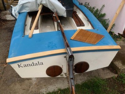
What’s aft.So this will be the the Rowlock Position which will be about 13 inches aft of the rowing seat
View attachment 197172
Similar to Daft but missing the DWhat’s aft.
Over lapped with #84 - 'centre main (sheet) system' will be well out of the way of the outboard. The ropes going through pulleys on each quarter are the spinnaker sheets. - Just need to set outboard clear of the rudder when it turns
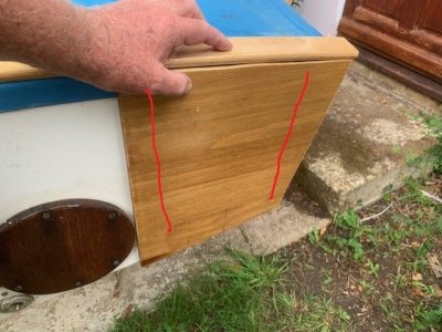
Thanks Keith. The outboard is such that should it hit the ground it would flip upwards. I will make a sandwich of the fiberglass 'transom'. This being the piece of wood shown and on the inside where the stainless bolts go through there will be a 10 mm or greater cut chopping board in that hard plastic from QD. Both will be stuck with CT1 as well as bolted. Remember I am not an Engineer so the factor of safety will only be about 1.5Make sure the aluminium bits and fixings for the outboard bracket are strong enough - especially for if the motor hits the ground at speed or gets caught up in something.
As you say - Laser type mainsheet system, but my GP 14 of similar vintage had a centre main - they all did then - may need a stiffer boom eventually if you bend it.
")
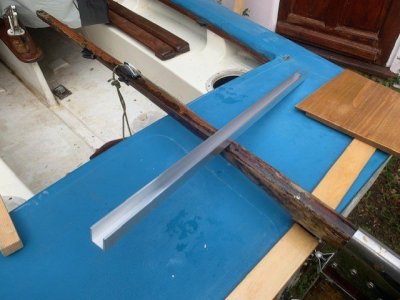
The wood in the picture will be permanently fitted to the rear of the boat. The ali channel will be cut into 2 lengths approx 250 mm long and permanently fixed to the wood you see in a gentle v. I will then make a board that will slide in and out of the channel to the thickness of the channel. The v Shape layout will stop the board just falling through and into the water. This board will extend say 100 mm above the top deck of the boat. It is this 100 mm high bit that I will clamp the outboard onto. If not using the motor the board that slots into the channel can be removed and used to wack an Engineer over the head with lolCan't quite see - Is the board extending above the transom a bit to take the clamps - simples if it is - not sure what the aluminium bits are going to do - awaiting final image with motor fitted.
As long as the prop and cavitation plate are just below water when static, with you both sitting in the boat, the propellor will draw the stern down deeper when it is running - our Yamaha 2B did ,

lolThe wood in the picture will be permanently fitted to the rear of the boat. The ali channel will be cut into 2 lengths approx 250 mm long and permanently fixed to the wood you see in a gentle v. I will then make a board that will slide in and out of the channel to the thickness of the channel. The v Shape layout will stop the board just falling through and into the water. This board will extend say 100 mm above the top deck of the boat. It is this 100 mm high bit that I will clamp the outboard onto. If not using the motor the board that slots into the channel can be removed and used to wack an Engineer over the head with lol