DIY antenna

Calmoceans

New member
Joined
22 Aug 2023
Messages
2
Visit site
Hi all, great forum, normally only read but have been getting slightly confused reading some of the internet so thought I'd ask a question.

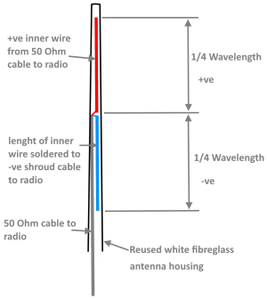
I had been having issues with vhf antenna, finally decided I needed to replace the antenna. Would the following work well for receiving as well as transmitting or is there something that I'm overlooking? Any simple improvements that I could make? Thanks.
1692696311382.png
 

andsarkit

Well-known member
Joined
27 Aug 2015
Messages
1,258
Location
Dartmouth
Visit site
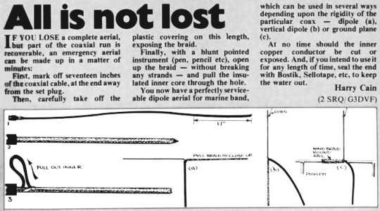
That is a fairly standard way to make an emergency antenna. If you strip off the outer insulation and tease the core from inside the braid at the cut point the braid can make one arm and the core the other. This will not involve any soldering. It will not be quite as good as a decent commercial one.
Lots of information online with some performance figures.
DIY antenna
It is usual to make the arms a little shorter than 1/4 wavelength to allow for end effects. Ideally you will have or borrow a VSWR meter to check it is performing well. The meter would also enable you to fault find on your existing system in case it is a coax or connector fault and not the antenna.
 

Minerva

Well-known member
Joined
16 Oct 2019
Messages
1,347
Visit site
Similar to Antarctic Pilot, that's how I made my AIS antenna. Only difference is that I used a 20(?)mm pvc plumbing pipe as the antenna cover with a bicycle handlebar end plug as the plug on the top of the casing.

Works perfectly well!
 

Calmoceans

New member
Joined
22 Aug 2023
Messages
2
Visit site
Thank you for your responses. Checking things with a vswr meter does sound sensible.

What to commercial suppliers do differently to make them better?

Thanks
 

William_H

Well-known member
Joined
28 Jul 2003
Messages
13,987
Location
West Australia
Visit site
Thank you for your responses. Checking things with a vswr meter does sound sensible.

What to commercial suppliers do differently to make them better?

Thanks
This is a quarter wave antenna. Works perfectly. However some commercially made antennae are 5/8 or more wavelength tuned to get correct impedance matching. The longer antenna gives a radiation pattern more pronounced to the horizontal and less radiated towards the vertical. That focussing of the radiation gives more power outwards and less wasted to the sky or sea. Hence claim decibels of gain. Fine however on a sailing boat inclined to heel it can actually focus power into water or sky when heeled. Doesn't seem to matter in real world however. Any antenna will be just as good or bad transmitting as receiving except when transmitting many transmitters will reduce power when VSWR is not good. ol'will
 

st599

Well-known member
Joined
9 Jan 2006
Messages
7,529
Visit site
This is a quarter wave antenna. Works perfectly. However some commercially made antennae are 5/8 or more wavelength tuned to get correct impedance matching. The longer antenna gives a radiation pattern more pronounced to the horizontal and less radiated towards the vertical. That focussing of the radiation gives more power outwards and less wasted to the sky or sea. Hence claim decibels of gain. Fine however on a sailing boat inclined to heel it can actually focus power into water or sky when heeled. Doesn't seem to matter in real world however. Any antenna will be just as good or bad transmitting as receiving except when transmitting many transmitters will reduce power when VSWR is not good. ol'will
It's a half wave dipole. The beam pattern will be even more pronounced in the horizontal. The only issue I can see is that you have an unbalanced feeder into a balanced antenna, there should be a balun transformer in there.
 

fisherman

Well-known member
Joined
2 Dec 2005
Messages
19,675
Location
Far S. Cornwall
Visit site
I have made two 'slim jim' antennae. Worked for me, but only on my home station, plenty of range receives Ushant. First one made from 8mm copper pipe tacked to a batten, pushed up a white sink drain pipe. Recent one made from S/S wire from a morse cable, rigid enough to maintain shape hanging in a tree. Not so good, but I need to revisit the calc. Had to use a terminal to affix the wire
Slim Jim and J Pole calculator – M0UKD – Amateur Radio Blog
 

john_morris_uk

Well-known member
Joined
3 Jul 2002
Messages
27,864
Location
At sea somewhere.
yachtserendipity.wordpress.com
If you want to get really technical the 1/4 wave mounted on an conductive horizontal plane (just imagine it sticking up out of a sheet of metal) presents an impedance (think of it as ‘resistance’ to the radio signal) of about 36 ohms vs the 50 ohms required. If the ground plane drops away all round the vertical at about 45 degrees then the impedance rises to close to the required 50 ohms. The wire vertical antenna as described will not be 50 ohms but it’ll probably work ok. Its actual impedance will depend on a number of factors.

It still won’t be as efficient as a 5/8 vertical because 5/8 verticals squeeze the signal more horizontally. You can squeeze it even more with other designs (eg colinear etc) but 5/8 is a good compromise for a sailing boat that heels. It’s why nearly all Marine VHF antennas are 5/8.

Homemade or commercial makes no difference as far as the radio waves are concerned but a 5/8 requires a matching device at the base to ensure 50 ohms impedance and although not impossible to make they’re more difficult to set up without instrumentation. The advantage of commercially made is that it might be neater and more weatherproof.
 

st599

Well-known member
Joined
9 Jan 2006
Messages
7,529
Visit site
I have made two 'slim jim' antennae. Worked for me, but only on my home station, plenty of range receives Ushant. First one made from 8mm copper pipe tacked to a batten, pushed up a white sink drain pipe. Recent one made from S/S wire from a morse cable, rigid enough to maintain shape hanging in a tree. Not so good, but I need to revisit the calc. Had to use a terminal to affix the wire
Slim Jim and J Pole calculator – M0UKD – Amateur Radio Blog
You can also make slim jim antennas from ladder line cables. Making a Basic Slim Jim 2m Antenna | Essex Ham

There's a helpful online calculator for the dimensions linked from that site.
 

john_morris_uk

Well-known member
Joined
3 Jul 2002
Messages
27,864
Location
At sea somewhere.
yachtserendipity.wordpress.com
I'm pretty sure you can make a 5/8 antenna at home out of electrical cable if you want to.
Of course you can, but getting it to match to 50 ohms impedance is the tricky bit. Not impossible by any means but it’s not really a simple matter of measuring and cutting.

You benefit from a lower more squashed angle of radiation all round too.
 

Gsailor

...
Joined
30 Sep 2022
Messages
1,337
Visit site
Thank you for your responses. Checking things with a vswr meter does sound sensible.

What to commercial suppliers do differently to make them better?

Thanks
That is a good question.

I bought a Metz aerial as a back-up because it was supposed to be the best. It has a large cylinder at the base which K hope has special bits in it to make it super good ... ?
 

William_H

Well-known member
Joined
28 Jul 2003
Messages
13,987
Location
West Australia
Visit site
It's a half wave dipole. The beam pattern will be even more pronounced in the horizontal. The only issue I can see is that you have an unbalanced feeder into a balanced antenna, there should be a balun transformer in there.
Yes to be pedantic the antenna described above is a half wave dipole if you count the ground wire stretched out in opposite direction to active part. If you used a large mass of metal at the bottom of the active part that might be described as 1/4 wavelength although the whole thing is essentially the same.
Now regarding the half wave antenna as considered a balanced load connected to an unbalanced feed line. I don't know how to explain or argue the difference except to say Balun is never used at this point. Perhaps safer to see the half wave antenna as essentially unbalanced.
My own main antenna on the trailer sailor uses an extended pole on push pit up about .5 metre with quarter wave whip out of the top. The coax ground shield connects to the top of the ss pole (ground plane) while centre wire connects to whip wire. (1/8 ch thick rod 17 inches long) works well with decent VSWR.
ol'will
 
Top