NASA BM2 Problem

Esmerelda

Member
Joined
30 Oct 2009
Messages
150
Visit site
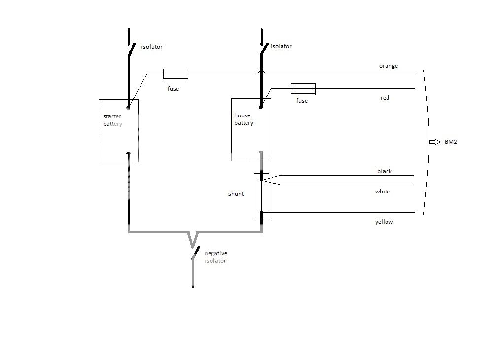
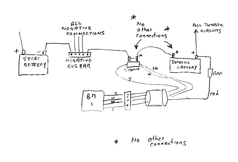
I tried fitting a NASA BM2 battery monitor today and ended up with a strange problem. When batteries were being discharged, the monitor showed it as charging and when I charged the batteries via the alternator it showed as discharging. The actual amounts of the ampage looked about right, it was the direction the monitor thought they were going in that was wrong!

Is anyone able to point me in a direction to look?

Thanks
 

theoldsalt

Active member
Joined
24 Nov 2010
Messages
2,113
Location
Bristol
Visit site
The monitor measures the current through the shunt fitted to the negative terminal of the battery. The white and black wires both go to the shunt terminal nearest the battery negatve post and the yellow wires goes to the other (domestic negative load) side of the shunt.
If charge and discharge readings are reversed maybe you have wires crossed. http://www.nasamarine.com/images/Clipper BM1+BM2.pdf
 

Ric

Well-known member
Joined
8 Dec 2003
Messages
1,723
Visit site
Sound like you have connected the shunt to the positive terminal of the batteries. On the NASA BM-2, the shunt should be connected to NEGATIVE terminal.

Excellent bit of kit by the way!
 

Esmerelda

Member
Joined
30 Oct 2009
Messages
150
Visit site
The shunt was connected to the negative terminal.

Could the fact that I had connected the battery monitor to the positive / negative just before the battery on / off switch rather than the battery terminals be a factor? (I know this isn't the right place to connect, but for the sake of convenience I thought I'd try it as the boat is new to us and I was struggling to see where the positive and negative battery cables went from battery to battery)
 

pvb

Well-known member
Joined
16 May 2001
Messages
45,604
Location
UK East Coast
Visit site
The shunt was connected to the negative terminal.

Could the fact that I had connected the battery monitor to the positive / negative just before the battery on / off switch rather than the battery terminals be a factor? (I know this isn't the right place to connect, but for the sake of convenience I thought I'd try it as the boat is new to us and I was struggling to see where the positive and negative battery cables went from battery to battery)

Do you have an on/off switch in your negative lead?
 

Esmerelda

Member
Joined
30 Oct 2009
Messages
150
Visit site
It's a Sun Odyssey and has 3 battery switches, 2 red (engine and domestic batteries) and 1 black. The black switch was described as a negative general cut-off switch. I connected the BM to the terminals on the back of those switches on the side connected to the batteries
 

pvb

Well-known member
Joined
16 May 2001
Messages
45,604
Location
UK East Coast
Visit site
It's a Sun Odyssey and has 3 battery switches, 2 red (engine and domestic batteries) and 1 black. The black switch was described as a negative general cut-off switch. I connected the BM to the terminals on the back of those switches on the side connected to the batteries

If you did that, wouldn't the monitor register current in and out of all the batteries, rather than just the domestic batteries? If you want it to work as intended, you need to follow Nasa's wiring diagram.
 

theoldsalt

Active member
Joined
24 Nov 2010
Messages
2,113
Location
Bristol
Visit site
Thanks for reply - unfortunately that is not the answer - I had even tried swapping them around in desperation...

...... but are you sure you have wired the BM2 correctly to the wiring diagram as referenced in post 2. It should be followed exactly for correct operation.
 

Esmerelda

Member
Joined
30 Oct 2009
Messages
150
Visit site
I appreciate that the way I tried wiring it means it may not be 100% accurate, my question was really why would it effectively be working backwards?
 

VicS

Well-known member
Joined
13 Jul 2002
Messages
48,217
Visit site
I appreciate that the way I tried wiring it means it may not be 100% accurate, my question was really why would it effectively be working backwards?

If it's reading back wards its because you have BM connection to the shunt incorrect

Connect the red and orange wires ( via fuses) to the house and starter battery +ve terminals respectively

Connect the shunt between the house battery negative and the negative isolator.

Connect the black and white wires to the end of the shunt that is connected to the battery and the yellow wire to the end connected to the negative isolator

There must be no other connections to the house battery negative terminal

NO IFs, NO BUTs ........ Like this:

bm2.jpg
 
Last edited:

VicS

Well-known member
Joined
13 Jul 2002
Messages
48,217
Visit site
The correct wiring diagram was referenced in the manual in my post 2 so a hand written diagram is hardly clarifying things for the OP.


The pictorial representation of the wiring to which you refer in #2 does not show the battery isolating switches, inparticular the common negative isolator.

It is not absolutely clear from goliaths posts quite how he as wired the shunt to the battery negative and the negative isolator. My diagram clarifies how that should be.

I am so sorry a hand drawn diagram is not good enough for you.!
I am just hoping it might help to clarify something that your post #2 and reference to the illustration in the instruction manual. which he doubtless already has, clearly failed to do..
 
Last edited:

mjf107

New member
Joined
13 Mar 2004
Messages
125
Visit site
The pictorial representation of the wiring to which you refer in #2 does not show the battery isolating switches, inparticular the common negative isolator.

It is not absolutely clear from goliaths posts quite how he as wired the shunt to the battery negative and the negative isolator. My diagram clarifies how that should be.

I am so sorry a hand drawn diagram is not good enough for you.!
I am just hoping it might help to clarify something that your post #2 and reference to the illustration in the instruction manual. which he doubtless already has, clearly failed to do..

Well I've made a copy of it for future reference..... A picture paints a thousand words
 

VicS

Well-known member
Joined
13 Jul 2002
Messages
48,217
Visit site
Well I've made a copy of it for future reference..... A picture paints a thousand words

The important point to remember is that there must be no other connections to the (house) battery negative, or the end of the shunt connected to it, as noted on one of my earlier hand drawn offerings ( From pre starter battery monitoring days...... No orange wire)

scan0058.jpg
 
Top