Wish me luck 2 - of to view 38ft boat in Sweden

Refueler

Well-known member
Joined
13 Sep 2008
Messages
18,930
Location
Far away from hooray henrys
Visit site
But would you trust it after so many years in possibly dubious storage conditions?

Its not actually the storage of it that turns me away from it.

The boat is 1986. I have no idea whats she been through since the day it was built. Would I be happy to lift her by those brackets on keel bolts ?

My thoughts are to be kind to the boat and use the common two sling approach.
 

penfold

Well-known member
Joined
25 Aug 2003
Messages
7,732
Location
On the Clyde
Visit site
From a load distribution perspective lifting on the eyes with strops is kinder if it's a crane lift, especially without a spreader bar. Few hulls are optimised for slings around the outside and if attention is not paid there's risk to log impellors, sail drives, prop shafts etc.
 

Refueler

Well-known member
Joined
13 Sep 2008
Messages
18,930
Location
Far away from hooray henrys
Visit site
From a load distribution perspective lifting on the eyes with strops is kinder if it's a crane lift, especially without a spreader bar. Few hulls are optimised for slings around the outside and if attention is not paid there's risk to log impellors, sail drives, prop shafts etc.

I agree with mid to large boats that spreader bars are advised .. but my 25ftr lifts without spreader bars fine .....

The lifter at our local yard does not pressure the sides in any way ....

Here's my 25ftr in slings ... craned as usual

dULmcfol.jpg


Then by local marina for the keel repairs ..

wFesMJDl.jpg


That same lifter will lift the 38 late september ... and yes - I will need to pull both speed logs just before ...
 

Refueler

Well-known member
Joined
13 Sep 2008
Messages
18,930
Location
Far away from hooray henrys
Visit site
We all find ways designs drive you nuts !!

The autopilot pin mount is on the cockpit coaming and when we were bringing her across from Sweden - when we tried the TP ... found the mount loose.
Days later when we were checking - found that the nuts had unwound and fell off the machine screws .... of course nuts have dissappeared into the depths somewhere of the transom locker.

I bought new nuts and bolts as the old were UNF .... not a usual format here ...

Mount has a plate above and a plate under as backing ... with three bolt / nut combos.

I empty transom locker and squeeze in as best I can to try and place backing plate and start the nuts ... no chance. Need skinny long arms to get up into the U of the cockpit sides. So what to do ??

Hit on an old trick ..... Bolted all together so they line up properly .... then using Super Glue and Kicker ... I literally 'welded' the nuts to the plate making sure nothing got through to the threads.

fSE7uBfm.jpg


Then two bolts reversed through the nuts ... then rod through one cockpit hole as guide to empty hole in plate .... climbed into locker .... pressed plate into position so that bolts now protruded ... friction luckily holding it in place. I then put nuts on two bolts ... tightened to get plate really into position.
Removed rod .... one bolt through mount into that empty nut ... then removed one reversed bolt ... wound down other bolt to flush with coaming ... turned mount so now it matched the three holes ... second bolt in ... third bolt in ............ tighten up ... jobs a flyer !!!

QHowVKBm.jpg


Yes that is my AH1000 ... but the AH2000 is still on board if the 1000 cannot handle it. Just need to transfer the rod extension over.
 

Refueler

Well-known member
Joined
13 Sep 2008
Messages
18,930
Location
Far away from hooray henrys
Visit site
Another old trick to get such plate and 'welded' nuts into place .... two long thin bent end rods ... The bent ends must be able to pass through the backing plate hole / nut.

Pass the two rods down through the holes in coaming till you see them below .... put through two corresponding holes / nuts of plate and TURN rods so the bent ends can pull the plate up into position ...

One bolt then used in the third position to hold it in position - while you remove ONE rod ... bolt through mount into plate etc. ... remove holding bolt - then swing mount round - second bolt ... remove last rod ... bolt in and tighten.
 

Refueler

Well-known member
Joined
13 Sep 2008
Messages
18,930
Location
Far away from hooray henrys
Visit site
Getting a bit annoyed with another matter ...

Seller had a nice Pioneer car system fitted at nav station ... and two multi speakers set into main fwd cabin bulkhead .... BUT never had them connected. It has power - but no speaker leads found anywhere near radio.
The speakers have leads going into the woodwork - so they must be somewhere .....

I really do not fancy removing panels as I find they often do not go back quite the same. Surely if the leads were led behind the edging of the woodwork they must have ends coming out where needed or close by ??? Surely not just poked behind and closed up !!!
 

Refueler

Well-known member
Joined
13 Sep 2008
Messages
18,930
Location
Far away from hooray henrys
Visit site
Went to boat today and had another poke around to find where cables transit ...

Found an inspection panel above stbd aft bunk - inside was the 0183 connections ... as well as the B&G Network box.
Various other in there based on the cables from mast.

No speaker wires ! TBH - why would anyone run them aft - to then run fwd again ?

Having checked B&G cables were fine there - I decided to open up the Hatch Garage panel holding the B&G displays. As I pulled the panel out - the 3 pin lower of three cables fell off ... no-one had turned the locking nut. Display read ERROR .....
Plugged back in .. still ERROR. Switched off system ... switched back on ... same daft 180+ m reading ...

According the book - if any fault in signal - it will read ERROR. If it shows the ----- or a reading then its connected ok and signal is received.

I have noticed though ... the setup flicks from data source E to F and back at times for no apparent reason ... as far as I know there is only the Airmar transducer connected. So why the swapping from E to F and back again ?
 

Refueler

Well-known member
Joined
13 Sep 2008
Messages
18,930
Location
Far away from hooray henrys
Visit site
DAFT DAFT DAFT !!!!

I stupidly assumed that the Airmar P79 transducer was for the B&G system ...

Its for the Garmin 70 UHD Echomap Plotter !! We never had overlays enabled - so next visit - will be investigating that.

Therefore that other transducer must be the B&G one ...... sitting centreline ...

3kbQLLfl.jpg


Hope that when I pull it - its IN hull and not through !!

The two behind it have blank plugs ready to use .. but not that centre one.

This can explain the comment by seller that he thought transducer needed fluid ... when I checked the Airmar - it was full ...
 

Refueler

Well-known member
Joined
13 Sep 2008
Messages
18,930
Location
Far away from hooray henrys
Visit site
OK ... confirmed I was on wrong track ....

The Airmar is providing depth signal to the Garmin MFD .... fired it up and selected split screen etc ....

eED8SiUl.jpg


Don't worry about the cluttered display ... it was just a quick select to see it work ... I'll refine it later sensible display.

This then led to further investigation of the other three 'ducers ..... each having a faded B&G cable tag ... the centre fwd of the three still readable serial no. 610-0A-027 .... definitely depth according to B&G Legacy list.
The two 'ducers aft of that - have similar B&G tags but unreadable serial no's but cables have red (port) green (stbd) taped round.

The Dial echo sounder has two cables coming to it and appears to be from those two ... as there is a switch fitted to top with Red / Green tabs. The two cables plug into back with Red / Green tabs.

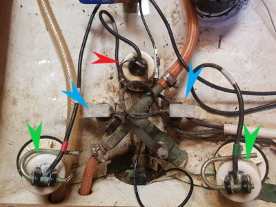
So my question is - where is the speed log ? Maybe its the two very small black items seen just behind the centreline 'ducer ??

This setup is really confusing ... especially that switch panel has Red / Green switching as well - which is connected to that strange big blue box ... but nothing changes when switches changed ...

At least I have depth reading again ... but would be nice to get the hatch garage display working properly.
 

penfold

Well-known member
Joined
25 Aug 2003
Messages
7,732
Location
On the Clyde
Visit site
You could pull the unknown devices and look, then it's definitive.

Red will be a depth sensor as it's squint, as will Blue; I can't see why anyone would glass a log in, although it's not impossible they might be ultrasonic or even less likely electromagnetic logs. Green probably speed as they are aligned fore and aft, perhaps the mystery box is an averaging device rather than just a switch.

sensor.png
 

Refueler

Well-known member
Joined
13 Sep 2008
Messages
18,930
Location
Far away from hooray henrys
Visit site
You could pull the unknown devices and look, then it's definitive.

Red will be a depth sensor as it's squint, as will Blue; I can't see why anyone would glass a log in, although it's not impossible they might be ultrasonic or even less likely electromagnetic logs. Green probably speed as they are aligned fore and aft, perhaps the mystery box is an averaging device rather than just a switch.

View attachment 162378
You could be right .... all I can say is so far it points to :

The Green are likely the switchable sounders ... note the red and green tapes respectively which agree with the switch panel + flasher sounder at nav table

NWP1rNUl.jpg


d1fPFgXl.jpg


.... the Red is the B&G sounder as the serial number checks out with their legacy list.

What I have difficulty with now is how the speed is being determined and I suspect that the Blue are electromagnetic ... but there are no markings or ID's to check out ....

I don't want to pull anything until lift out and if I am right about the 'ducers - then it appears that I may not have to pull them to avoid lifting strop. I only have plugs tethered to the two rearward 'ducers ... that fwd centre one has no plug so I am loathe to risk it. Thoser two plugs themselves create questions .. why if its sounders ??
 
Last edited:

Refueler

Well-known member
Joined
13 Sep 2008
Messages
18,930
Location
Far away from hooray henrys
Visit site
Today sorted out the Garmin .... still not too keen on it !!

Removed the old Sounder and put my Plotter / AIS in its place at the nav station ... all working nice

Finally got the 'blue box' opened up ......

9RQXbUdl.jpg


BKWSOhil.jpg


Inside case :

dzKrwVCl.jpg


Its a mess of capacitors and couple of boards bolted together - will be trying to contact ELFA.SE to see what they say ...
 

Alex_Blackwood

Well-known member
Joined
19 May 2003
Messages
1,688
Location
Fareham
Visit site
Today sorted out the Garmin .... still not too keen on it !!

Removed the old Sounder and put my Plotter / AIS in its place at the nav station ... all working nice

Finally got the 'blue box' opened up ......

9RQXbUdl.jpg


BKWSOhil.jpg


Inside case :

dzKrwVCl.jpg


Its a mess of capacitors and couple of boards bolted together - will be trying to contact ELFA.SE to see what they say ...
I will be surprised if ELFA can help, Looks like the box is theirs but the innards look home made. Sorry, wish I could be of more help!
 

Refueler

Well-known member
Joined
13 Sep 2008
Messages
18,930
Location
Far away from hooray henrys
Visit site
Connected NMEA2WiFi box .... to test ... all good ....

That's now Garmin MFD (Echomap UHD 70) ... Onwa KP39A .... Smartphone .... Tablet ..... Acer One Notebook all rec'g AIS and other data fine. With WiFi available as well.

I may revert the NMEA2WiFi back to the other boat and invest in the higher spec NMEA4WiFi unit ....

Next job is to swap out the excellent but non DSC Sailor VHF set for a full GPS / DSC VHF I have spare ...

Only limitation at present is that I am still awaiting Swedish Registry so I can register for MMSI / Call Sign etc.
 

andsarkit

Well-known member
Joined
27 Aug 2015
Messages
1,189
Location
Dartmouth
Visit site
Yep - as expected - Elfa say the K441 is just the box ID and they have no idea what was placed inside of it.
The pcb marking in the photo is just a manufacturers part number for a standard piece of stripboard. It looks like it could be a sensitivity adjustment for the relay switching.
Is there another pcb underneath that looks like a proper designed board?
 

Alex_Blackwood

Well-known member
Joined
19 May 2003
Messages
1,688
Location
Fareham
Visit site
The pcb marking in the photo is just a manufacturers part number for a standard piece of stripboard. It looks like it could be a sensitivity adjustment for the relay switching.
Is there another pcb underneath that looks like a proper designed board?
Difficult to say, that board also looks as though it has been cut to fit. I think first step should be. Determine which switch ? powers up the unit. Then find out what "Data" inputs there are and how many. Then what data outputs there are and , again, how many, where do they go? Anything else is speculation without getting "hands on" However just to speculate, could it be some version of a "Digital/Analogue convertor? Do the inputs come from the Red and Green labelled units?
I would love to dig into it. Great when you get that "Eureka" moment! :oops:
 

Refueler

Well-known member
Joined
13 Sep 2008
Messages
18,930
Location
Far away from hooray henrys
Visit site
There are two boards .... both loaded with components ....

I have tried finding what energises the 'box' ..... nothing.

But the multi core cable is connected to a number of switches on the panel - but nothing happens when used !

I suspect the box is a hangover from a previous installation ... but afraid to start disconnecting things !!!
 
Top