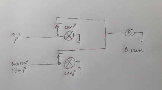
Looking for schematic on beeper

pelissima

Member
Joined
7 Aug 2002
Messages
400
Location
Athens Greece
Visit site
Hi All,
I would like to install the missing beeper on our First38, with Perkings 4108.
Would someone be so kind so as to provide me with wiring schematic on how this should be connected in order to work on par with the green and yellow lights on the engine panel?
Thank you in advance
 

wonkywinch

Well-known member
Joined
30 Jul 2018
Messages
2,036
Location
Hamble, UK
Visit site
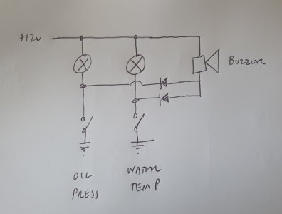
If this is a new addition, I'd simply add diode fed circuits from the warning lights to a buzzer like this.

Cheap as chips 1N4001 diodes will do the job.

20230930_141959.jpg
 

andsarkit

Well-known member
Joined
27 Aug 2015
Messages
1,258
Location
Dartmouth
Visit site
I don't know the details of the 4108 but oil and temperature switches usually go to ground when activated. this will mean you need to reverse the diodes and put 12v rather than 0v onto the buzzer. The circuit is then completed when the switch connects to the engine block.
 

Refueler

Well-known member
Joined
13 Sep 2008
Messages
20,464
Location
Far away from hooray henrys
Visit site
Which BEEPER is this ? Is it the simple power is on - but engine not started beeper ? Then that is based on the alternator exciter lead.

Basically - when engine is not running - alternator is not supplying voltage. The BEEPER then sounds as voltage is +12ve .... but once engine starts and alternator comes on charge - the exciter lead goes to 0 ... BEEPER stops sounding. Its same as the ignition red light in a car.
 

rogerthebodger

Well-known member
Joined
3 Nov 2001
Messages
13,526
Visit site
When the alternator is running (charging) the excitation lead goes to 12 Vdc

he charging light on a car does out because the one side on th light is at 12V and the other connected to the excitation liput to the alternator is at 0 when engine not running but goes to 12v when engine is running and thus the charging light goes out

The buzzer could be connected across the ingestion light if the OP wished it to operate that way
 

Refueler

Well-known member
Joined
13 Sep 2008
Messages
20,464
Location
Far away from hooray henrys
Visit site
When the alternator is running (charging) the excitation lead goes to 12 Vdc

he charging light on a car does out because the one side on th light is at 12V and the other connected to the excitation liput to the alternator is at 0 when engine not running but goes to 12v when engine is running and thus the charging light goes out

The buzzer could be connected across the ingestion light if the OP wished it to operate that way

Oh dear here we go ....

The Exciter lead has 12v from battery ... - buzzer sounds .... When alternator spins up and powers - it puts out 12+v that opposes the 12v on the exciter lead - making it zero ... buzzer stops.

Reason I mention it - is because OP is vague on what buzzer he's talking about ... as 4-107 user - the buzzer is usually for alternator ....
 

rogerthebodger

Well-known member
Joined
3 Nov 2001
Messages
13,526
Visit site
The excitation lead will be at 0 volts the 12 volts is connected to the the other side of the ingestion light so current will flow from the 12 v to through the light to the excistion lead which with the alternator NOT running will be a 0 (ground)

When alternator runs the voltage on the excitation line will become 12 v due to self excitation of the alternator

The voltage on the excitation connection on the alternator will be 12 V as will the voltage on the input side of the charge light.

The voltage across the charging light will be 0 (12v - 12v)

My reading of the OP is as described by wonkywinch

An extra diode could be added to do what you suggest with the 12v conning from the ignition switch so no light or buzzer operates until ignition switch is turned on

This is how my engine set up works built by myself

My diodes are in fact LED's so no separate light as the diode /LED perform the same function as both
 

wonkywinch

Well-known member
Joined
30 Jul 2018
Messages
2,036
Location
Hamble, UK
Visit site
My Beneteau has a Yanmar with B20 control panel and warning lights/audible buzzer to warn of lack of battery charge, low oil pressure, high coolant temperature and water in sail drive.

I'm adding a high exhaust mixer temperature sensor into the audio alarm with it's own red warning light near the engine panel/throttle using a cheap electronic thermometer and diode in the circuit as above.

Just need to look at the B20 circuit to see how the lights/buzzer is triggered, ie +12v or pull to ground.

The reason for my addition is early warning of blocked sea water, plastic bag, seaweed etc as the standard engine temp alarm might be too late to have already caused engine damage if coolant starvation occurs.
 

pelissima

Member
Joined
7 Aug 2002
Messages
400
Location
Athens Greece
Visit site
My Beneteau has a Yanmar with B20 control panel and warning lights/audible buzzer to warn of lack of battery charge, low oil pressure, high coolant temperature and water in sail drive.

I'm adding a high exhaust mixer temperature sensor into the audio alarm with it's own red warning light near the engine panel/throttle using a cheap electronic thermometer and diode in the circuit as above.

Just need to look at the B20 circuit to see how the lights/buzzer is triggered, ie +12v or pull to ground.

The reason for my addition is early warning of blocked sea water, plastic bag, seaweed etc as the standard engine temp alarm might be too late to have already caused engine damage if coolant starvation occurs.
This seems to me to be a very good idea. I would even show, I imagine, an impeller loosing a feather but still working,
 
Top