TheCoach
Active member
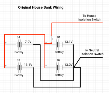
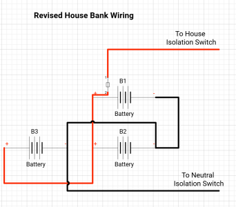
So having had the Antares 9.80 for 3 years now we are pretty convinced it does everything we need and can't find anything that suits our needs better. As a result I am planning on investing some hours and $'s this winter upgrading various components including the core wiring layout. Having read lots of contributions and great info from the likes of @PaulRainbow on here (and others) as well as Geoff Cote at Pacific Yacht Systems I thought I would use this post to not only ask lots of questions but also document the approach I am taking given there are probably quite a few "french" boats with similar setups that could do with upgrading 
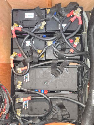
So just as a bit of background its a twin engine motorcruiser with 2 engine batteries (140aH) and a house bank made of 4 x 85aH - all FLA as far as I can tell.
The batteries run to the normal Beneteau/French boat isolation/switch panel that includes 2 x engine isolators, a house isolator, a common neutral isolator and a battery combiner for the 2 engine batteries
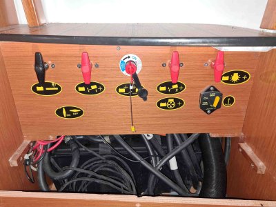
Part of the reason for simplifying and upgrading is when you look at the back of the switch panel you will see an absolute mess, no busbars in sight, multiple stacked terminals on one switch etc etc. Also in classic boat builder fashion nothing is labelled and all the wires are either red or black
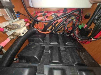
The initial reason for investigating is the house bank is foobar'd - only manages to last about 5 hours running the fridge and lights when at anchor. A couple of times I forgot to switch on the shore power when in the marina and drained the batteries, but I've not been able to identify where the parasitic drain is, so wanted to fit a shunt. Then looked at this and thought
So the plan is first off to try and identify the various circuits and draw up a new wiring diagram to help plan everything out and get the system set up properly before replacing the house bank (not mentioning the "L" word at the moment!)
So first couple of questions:
1. None of the battery to switch links seem to be fused. I am assuming best practice would be for all the connections to be fused, so would you fit MRBF type fuses to each battery terminal (inlcuding all the house batteries that are linked or just the final house battery bank terminals)?
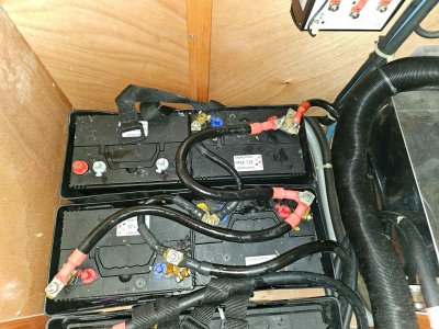
2. The battery cables are all in 95mm2 cable which seems massive overkill? They also are excessively long (see pic of under switches). Is there any need for this size of cable (probs not worth replacing but interested to know).
Next step, start building the circuit diagram........
Cheers,
TC
So just as a bit of background its a twin engine motorcruiser with 2 engine batteries (140aH) and a house bank made of 4 x 85aH - all FLA as far as I can tell.

The batteries run to the normal Beneteau/French boat isolation/switch panel that includes 2 x engine isolators, a house isolator, a common neutral isolator and a battery combiner for the 2 engine batteries

Part of the reason for simplifying and upgrading is when you look at the back of the switch panel you will see an absolute mess, no busbars in sight, multiple stacked terminals on one switch etc etc. Also in classic boat builder fashion nothing is labelled and all the wires are either red or black

The initial reason for investigating is the house bank is foobar'd - only manages to last about 5 hours running the fridge and lights when at anchor. A couple of times I forgot to switch on the shore power when in the marina and drained the batteries, but I've not been able to identify where the parasitic drain is, so wanted to fit a shunt. Then looked at this and thought
So the plan is first off to try and identify the various circuits and draw up a new wiring diagram to help plan everything out and get the system set up properly before replacing the house bank (not mentioning the "L" word at the moment!)
So first couple of questions:
1. None of the battery to switch links seem to be fused. I am assuming best practice would be for all the connections to be fused, so would you fit MRBF type fuses to each battery terminal (inlcuding all the house batteries that are linked or just the final house battery bank terminals)?
2. The battery cables are all in 95mm2 cable which seems massive overkill? They also are excessively long (see pic of under switches). Is there any need for this size of cable (probs not worth replacing but interested to know).
Next step, start building the circuit diagram........
Cheers,
TC

