Best Connections onto Batteries

dje67

Member
Joined
20 Sep 2007
Messages
337
Location
Largs
Visit site
I have 5 of these batteries, arranged into a bank of 2 and a bank of 3, with a single (at the moment) hand-off to the battery isolator switch. All batteries are in a 1m2 area, so quite close to each other.

https://cdn.tayna.com/datasheets/LDC12-115-G31-DT.pdf

The batteries have dual connectors on + and - I.e. the conventional round lug and a 3/8” threaded post.

2 questions for those that know such things:-

1) are the threaded posts (rather than the conventional round lugs) better in terms of losses/volt-drops when bringing each battery in a bank together, and for the final hand-off of each bank, which of the connections is best?

2) to equalise load on each individual battery, what is the best, low-resistance ‘pattern’ for bringing the whole bank up to the isolator? Feed each bank directly to the isolator (I.e. 2 feeds, one from each bank), or bring the 2 banks together on one of the banks before sending a single hand-off to the isolator? Same obviously applies to the -ve side of the bank(s).

Finally, I’m looking at using 70mm2 cables for all this. Might be overkill? Highest loads are windlass (around 90A) and an EasySolar charger/inverter 1300W continuous, say 130A. I want to minimise volt-drop as the fridge (at the end of a longish chain of switches and cables through the switch panel) gets upset if battery volts drop below 12.4V, when other loads kick-in.
 

Tranona

Well-known member
Joined
10 Nov 2007
Messages
40,972
Visit site
Use the studs. More secure and easier to crimp the lugs. my main batteries only have posts so I used post terminals with studs attached and used ready made cables. Why are they in 2 banks? surely you only want one for domestics? Link all 5 together and take the positive from one end of the bank and negative from the other. That makes the whole lot one battery. Presumably you have a separate start battery and a charge splitter of some sort for alternator charging. Solve the fridge problem by rewiring it either direct from the 12v distribution panel with 2.5mm2 cable.

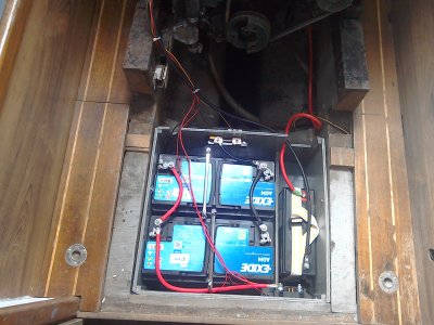
This is my battery layout (incomplete at this point but showing links). More basic but same principles.

IMG_20220413_150908.jpg
 

Boater Sam

Well-known member
Joined
14 Mar 2020
Messages
1,360
Location
Philippines and Thailand
Visit site
Take the positive and negative off from opposite ends of the battery bank so that the cables to each battery are nearly the same length and hence the same resistance, so that they all get the same charge and provide the same discharge current.
 

dje67

Member
Joined
20 Sep 2007
Messages
337
Location
Largs
Visit site
Use the studs. More secure and easier to crimp the lugs. my main batteries only have posts so I used post terminals with studs attached and used ready made cables. Why are they in 2 banks? surely you only want one for domestics?
It is all one domestic bank - just split into two bilge compartments (can't change that without a large hacksaw/grinder...!). 1st compartment has 3 batteries side-by-side. 2nd compartment has 2 end-on to each other. I recall reading somewhere that volt-drop along cables on a multi-battery bank can result in some batteries being worked harder than others. I guess I was wanting to make sure that I wasn't working either the 2-bank or the 3-bank harder than the other.

Link all 5 together and take the positive from one end of the bank and negative from the other. That makes the whole lot one battery. Presumably you have a separate start battery and a charge splitter of some sort for alternator charging.
Yes - I have a 6th engine start battery in my armoury. Currently manually switched onto a common busbar with the domestic bank (Beneteau did this in their 1990's boats). I'm intending to completely separate the engine start from the domestic bank with a VSR, but that's a future project.
Solve the fridge problem by rewiring it either direct from the 12v distribution panel with 2.5mm2 cable.
Fridge already has 4mm2 cables, but the overall round-trip from batteries, through isolators to switch panel, through switch panel switch then across to the fridge is about 12m. Adding up cable losses and drops across switches gives me about 0.5V less across the fridge controller than at the batteries. Did think about changing the cabling, but routing cables across the boat from the switch panel (on strb) to the fridge (on port) is near impossible (original cabling was built into the boat when constructed, with no obvious route available post-construction. Hence the reason I'm wanting to find any means of reducing volt-drops whilst I make some modifications to install an inverter.
This is my battery layout (incomplete at this point but showing links). More basic but same principles.

View attachment 155525
 

mil1194

Well-known member
Joined
1 Jul 2010
Messages
7,336
Location
Gower
www.myitmatters.com
Sorry if I’ve missed it, do you have 1 12v fridge or are you using the inverter to run it at 240v(which doesn’t seem a good idea!)

Sorry - you have a 12v fridge at the end of the cabling - what do you want your inverter to do?
 

dje67

Member
Joined
20 Sep 2007
Messages
337
Location
Largs
Visit site
Sorry if I’ve missed it, do you have 1 12v fridge or are you using the inverter to run it at 240v(which doesn’t seem a good idea!)

Sorry - you have a 12v fridge at the end of the cabling - what do you want your inverter to do?
Yup - one 12V fridge. Inverter (EasySolar) lets me greatly improve my charge rate (can do up to 70A into my 600Ah bank), as my old charger was not fully charging the bank (didn't have the correct charge profile for my lead carbon batteries). Easy solar also lets me experiment with using solar panels to help with charging. The inverter part of the EasySolar is mainly just for extra flexibility in running computer equipment, microwave, induction hob, hairdryer, power tools when afloat. Probably nothing that couldn't be done with faffing around with 12V cabling & sockets & adaptors, or continuing to rely solely on gas for cooking.

I also really like the bluetooth functionality on the Victron stuff - I quite like seeing exactly how the batteries are performing when away for several days without shorepower. But, with more info/data avilable you start to see things that need improving (even if they don't!).
 
Last edited:

Boater Sam

Well-known member
Joined
14 Mar 2020
Messages
1,360
Location
Philippines and Thailand
Visit site
Fridge already has 4mm2 cables, but the overall round-trip from batteries, through isolators to switch panel, through switch panel switch then across to the fridge is about 12m. Adding up cable losses and drops across switches gives me about 0.5V less across the fridge controller than at the batteries. Did think about changing the cabling, but routing cables across the boat from the switch panel (on strb) to the fridge (on port) is near impossible (original cabling was built into the boat when constructed, with no obvious route available post-construction. Hence the reason I'm wanting to find any means of reducing volt-drops whilst I make some modifications to install an inverter.
Nothing like thick enough, for a distance of 12m between batteries and fridge I would use 10mm cable at a minimum. Rule of thumb is 1mm per metre run.
 
Top