270ah DIY LiFePO4 build

vas

Well-known member
Joined
21 Jun 2011
Messages
8,077
Location
Volos-Athens
Visit site
thanks greg, didn't think of that :)
yes ordering from Amy, waiting for her formal quotation.
I guess her precut insulation will be the size of the cell, I want it around 70-80mm higher so that it creates an elevated insulation plane to make sure cells wont be squashed or tools dropped on top. But the chopping mats look fine and I guess the same bars that she'll supply will fit!

what do you mean design files? As I said that's the diyBMS and I took the EasyEDA files from another user and modded them a bit. All discussed here (ok, longish discussion):
DIYBMS for Lithium Iron Phosphate battery cells (LiFePo4) 280aH
 

gregcope

Well-known member
Joined
21 Aug 2004
Messages
1,621
Visit site
The JDB BMS has some anoying flashing leds that will such power overtime. I might remove them.

Charged voltage seems to settle around 3.33 volts with a 3mv delta.

Tomorrow I might work out how to use the capacity testor and make the wiring it might need.
 

vas

Well-known member
Joined
21 Jun 2011
Messages
8,077
Location
Volos-Athens
Visit site
8Χ304Ah EVE cells ordered, 1204euro + 36euro paypal surcharge., shipped to Greece.
Gives me two months to sort out the diyBMS and Victron connection so that I'll be able to get the victron doing the disconnect/reconnect/charge levels, etc. See how that will go!
BMS (in kit form arrives on Wed)

V.
 

Poey50

Well-known member
Joined
26 Apr 2016
Messages
2,315
Location
Chichester
Visit site
A quick note on UK insurers. There was a recent report that Topsail canceled insurance on being informed of a LFP upgrade. They apparently had no interest in arguments differentiating LFP from the less stable lithium chemistries. On the upside I have just heard that GJW Direct have no current issues with LFP as long as manufacturers' recommendations are followed. They do not require professional installation. This suits me as I changed to them last season although didn't make any point about informing them of my LFP system as they didn't seem to require it. I did think I might face some difficulty when the 10 years re-survey requirement is due in 2026 so this seems like good news.

It would be interesting to hear of any other insurance issues - good or bad - related to LFP.
 

gregcope

Well-known member
Joined
21 Aug 2004
Messages
1,621
Visit site
So my Frankenstein Prototype Mk1a is alive. However seems to suffer from significant internal power consumption as it goes flat in a few days and hits low voltage disconnect.

It is a nominal 7Ah pack. Most cells test around 5Ah on youtube. Seems cell 1+2 are more discharged as now Cells 3+4 are near high cell voltage cuttoff. Presently its bouncing off Cell Over Voltage protection (3.461 V, 3.462 V, 3.530 V, 3.528V). Later two are balancing.

Eventually got to 3.65 per cellish.

Think my cells are at the cheaper end of the spectrum ...
 

gregcope

Well-known member
Joined
21 Aug 2004
Messages
1,621
Visit site
Any general thoughts on Balancing at 3.4V and 10 mV deviation, with charger on/off, to 3.65v?

Logic is to start balancing as you hit the knee (on way up) and burn off the top 0.5% of capacity balancing back down.
 

gregcope

Well-known member
Joined
21 Aug 2004
Messages
1,621
Visit site
in reply to my own question a recent off gird solar garage youtube showed that Andy uses 3.45V balancer on, 1mv deviation and balancer on if charger off.
 

Travelling Westerly

Active member
Joined
20 Dec 2019
Messages
460
Location
Dorset
Visit site
My settings are absorption at 13.3 volts and float at 13.3 volts. As absorption is the same as float then absorption times don't mean anything. In practice, when the LFP drops below 13.3v then it will accept charge and when it reaches 13.3 v then it accepts no charge at all. Temperature compensation and equalisation are switched off.

My balance threshold is 3.4v per cell so 13.6 pack voltage and therefore there is no balancing at my storage voltage. Over several months this causes imbalance with my 123SmartBMS because each cell has its own board and cells 1 and 4 have a slightly higher current draw than 2 and 3. So I have to charge slowly to nearly full at the start of a new season to balance the pack and to re-set my battery monitors. Other BMSs may manage this better but I think that 13.3 volts is generally considered to be a safe storage setting. Rule of thumb is that anything below 13.4 volts doesn't bring LFP to full charge. Anything above 13.4 volts will eventually bring LFP to 100%
Ah that's interesting.
My settings are currently 14v absorbsion and 13.5 float. The original abs setting was 14.2v but both packs have cells that have runners that trip the Daly BMS towards the 14v final stage. The Victron Phoenix never got to the float stage as the BMS tripped just prior ( 1 cell in each pack reached 3.7v over voltage trip setting).
I've reduced the abs charge to 14v which has stopped one packs runner cell from reaching the over voltage point but the other pack still trips before reaching the float stage.
Your abs setting of 13.5v, does this mean the pack never fully reaches 100%? I think I've seen a set of published voltage tables somewhere that shows a 12v package is 95% or higher for 13.5v?
Does this mean you can leave the charger on all the time. I'm interested as I'm a liveaboard and basically my 240ah pack is charged, then used for about a week before it needs charging back up. My 300w solar is negligible this time of year so I'm wondering if I can just leave the mains charger on full time and it will pick up the house loads. But then I guess I'm into the realms of Lifepo4 don't like sitting at 100% for long periods.?
Top balancing was probably not done during manufacturing but its too late now so may have to live with a runner unless it calms down over more cycles?
 
Last edited:

Poey50

Well-known member
Joined
26 Apr 2016
Messages
2,315
Location
Chichester
Visit site
Ah that's interesting.
My settings are currently 14v absorbsion and 13.5 float. The original abs setting was 14.2v but both packs have cells that have runners that trip the Daly BMS towards the 14v final stage. The Victron Phoenix never got to the float stage as the BMS tripped just prior ( 1 cell in each pack reached 3.7v over voltage trip setting).
I've reduced the abs charge to 14v which has stopped one packs runner cell from reaching the over voltage point but the other pack still trips before reaching the float stage.
Your abs setting of 13.5v, does this mean the pack never fully reaches 100%? I think I've seen a set of published voltage tables somewhere that shows a 12v package is 95% or higher for 13.5v?
Does this mean you can leave the charger on all the time. I'm interested as I'm a liveaboard and basically my 240ah pack is charged, then used for about a week before it needs charging back up. My 300w solar is negligible this time of year so I'm wondering if I can just leave the mains charger on full time and it will pick up the house loads. But then I guess I'm into the realms of Lifepo4 don't like sitting at 100% for long periods.?
Top balancing was probably not done during manufacturing but its too late now so may have to live with a runner unless it calms down over more cycles?

The post you responded to got detached from the original context which was discussion on settings for storage. The settings hold the pack at mid-range about 60% charged but you have to experiment since the flat charging curve makes it tricky to match state of charge to voltage. For standard charging my target voltage is 13.8 volts, then the shortest period of absorption that can be fixed then charging over. 'Float' is set at a low figure such as 13.2 volts but that effectively means 'no charging' when applied to LFP.
 
Last edited:

gregcope

Well-known member
Joined
21 Aug 2004
Messages
1,621
Visit site
Top balancing was probably not done during manufacturing but its too late now so may have to live with a runner unless it calms down over more cycles?

Does your BMS do balancing? One trick I saw from Solar Garage is to charge at really low amps when nearly fully charged. Logic is that when charging at reasonable amps (1A or above. - ie 20x above balance current) that one cell "runsaway" and hits high cell voltage cutt off (as you are seeing) way before others.

Balancing is often configured to happen when charging (ie above 3.5v). As balancer currents can be really low (50ma? even) then charging at say 0.5A or what every the packs see as a charging amperage (to enable balancing) but low enough to allow the balancer to keep up with a cell that is trying to "runaway" by bleeding power away from it, whilst the other cells get charged and things level out.

Do you have a BMS with bluetooth where you can validate charge Amps and balancer being on (or just confirm its seeing charge?)
 

vas

Well-known member
Joined
21 Jun 2011
Messages
8,077
Location
Volos-Athens
Visit site
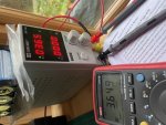
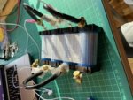
... and to keep the thread going, just managed to built and test my new BMS, diyBMS an open source project by a brit called Stuart. Well developed, you get the files to built your own pcbs (one per cell, similar to 123bms) and one controller board. 304Ah EVE cells ordered, will be here late Jan (at best!) so plenty of time to test the setup. Got 4 18650cells, 2 new 2 used, hooked them up and testing:

DSC_1823.JPG
works fine charges/passive balances/discharges as it should, quite impressed.
More impressive that it can talk to Victron kit via CANBUS, that's the task for w/e onwards!

cheers

V.
 
Top