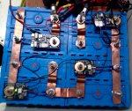
270ah DIY LiFePO4 build

Poey50

Well-known member
Joined
26 Apr 2016
Messages
2,309
Location
Chichester
Visit site
That's why a hybrid system appeals to me. Something like a gel battery in parallel with the LFP. BMS shuts down the FLP battery and the gel takes the load. Sure the kettle, hair dryer and windlass won't work. However, if you are at sea, then VHF chart plotter and AP should continue for sometime. If the engine or solar also continues to charge what's left of the house bank, it may not be a complete snafu.

If you are going to follow the Zwerfcat method Lithium-Hybrid although it looks straightforward it is worth noting that they are not using drop-in batteries but instead an external BMS of their own design. The method relies on the LFP being taken offline by the BMS when it is sufficiently charged and sufficiently discharged. It is a homeostatic system moving between lead acid and LFP making use of their different charging characteristics and theoretically works without a lot of user input. However the BMSs of drop-in systems have parameters not usually designed for this kind of use since they are generally set at higher and lower cell voltages. They will protect the battery from very serious damage but using them routinely in a Zwerfcat system would serious shorten their lives. Since drop-ins are the most expensive way of buying LFP then this would be a very costly method over time. Drop-ins don't have user-adjustment in the way that an external BMS has. You could certainly use a 123SmartBMS in a Zwerfcat system.
 
Last edited:

Pete7

Well-known member
Joined
11 Aug 2004
Messages
4,085
Location
Gosport
Visit site
If you are going to follow the Zwerfcat method Lithium-Hybrid although it looks straightforward it is worth noting that they are not using drop-in batteries but instead an external BMS of their own design.

Agreed, I have no wish to use a drop in LFP battery, particularly if its a fairly simple 12v set up. The tear down reviews by Will Prowse on some of the cheaper drop ins are just worrying. Can I build a better mouse trap? Don't know, but mine won't have great blobs of solder everywhere, or held together with expanding foam and sellotape.
 

Poey50

Well-known member
Joined
26 Apr 2016
Messages
2,309
Location
Chichester
Visit site
Really good on issues of float settings for LFP. Fortunately I arrived at the same conclusion for lockdown storage. I have both absorption and float on my Victron solar controller at 13.3v and this is maintaining my pack at 58% state of charge. I have an AGM start battery and a Victron B2B is keeping that at float. The whole system is now in good homeostatic balance.

 
Last edited:

Pete7

Well-known member
Joined
11 Aug 2004
Messages
4,085
Location
Gosport
Visit site
Yes. liked that, explained the problem really well and what to do about it if for example using solar. Book marked to watch again when world settles down a bit and I order some LFPs.

Pete
 

Poey50

Well-known member
Joined
26 Apr 2016
Messages
2,309
Location
Chichester
Visit site
Since Christmas three things have happened. I got an Arduino starter kit for Christmas, the lockdown has got more intense with a lot of time to fill, and a clever son who understands Arduino code has come home to bubble with us. The net result is a solution to something that came up earlier in this thread: how to remotely increase the SOC of an LFP pack, resting at mid-charge, prior to a longer trip. I've been testing a version of this in the shed, texting to get voltage from start and house batteries and opening and closing relays remotely (the small relays opening bigger ones) to allow solar charging to add to the domestic LFP SOC and also to activate remotely the B2B to keep the start battery charged from the LFP. It works so I'm happy to post the code if anyone is interested. The next step is to 3D print a housing for it. Costs so far are are under £40 with £6 per month for unlimited texts using a Giffgaff SIM which is backwards compatible with 2G. Smarty is a pound cheaper but is 3G and upwards.

EougbJyl.png
 
Last edited:

sailaboutvic

Well-known member
Joined
26 Jan 2004
Messages
9,983
Location
Northern Europe
Visit site
Well at last I too am a fully paid up member of the lithium build your own club.
It taken a while , but in the end I got there and thanks Poey for your input .
Couple of thinks I mention for people who looking at building your own cells .
Be patience when it comes to balance I had to do mine twice first time I stop too early thinking all the cells where the same at 3.5v even after leaving them at rest for 24hours but above that once they when in a 12v bank charging with solar the cell wondered off quite a lot.
Another lesson learned , I used the 123 smart BMS thinking it will balance the cells , the Smart is a passive balance so it doesn't do the job of balancing well if your cells are out , passive balancer just burn bit off the top of a cell , if I did it again I would buy a BMS with a
So anyone know of a Actve balance that can be used at the same time of the smart , I'm interested.
I also ended up making my own busbar as the once that came with the cells looks very thin .
Some thing else I learn is your can't charge there cells up to 14.4v without a risk of getting very close to the top , lucky for me I kept a very close eye on mine other wise it could had been a bundle of cells for the bin , I now have mine set at 14.1v ,
I may even set them lower depend on how things go with power uses and how quickly the solar charge them up .
At the moment I have my solar on to the batteries , still trying to find out if for some reason if the relay open and shut the power to the MPPT if the MPPT would get damage , some say yes others no waiting for a reply from Victron , once I know for certain then I will remove them from the batteries to the other side of the relay , other wise I have to find another way around it .
 

Attachments

  • IMG_3473.JPG
    IMG_3473.JPG
    852.5 KB · Views: 50

Poey50

Well-known member
Joined
26 Apr 2016
Messages
2,309
Location
Chichester
Visit site
Well at last I too am a fully paid up member of the lithium build your own club.
It taken a while , but in the end I got there and thanks Poey for your input .
Couple of thinks I mention for people who looking at building your own cells .
Be patience when it comes to balance I had to do mine twice first time I stop too early thinking all the cells where the same at 3.5v even after leaving them at rest for 24hours but above that once they when in a 12v bank charging with solar the cell wondered off quite a lot.
Another lesson learned , I used the 123 smart BMS thinking it will balance the cells , the Smart is a passive balance so it doesn't do the job of balancing well if your cells are out , passive balancer just burn bit off the top of a cell , if I did it again I would buy a BMS with a
So anyone know of a Actve balance that can be used at the same time of the smart , I'm interested.
I also ended up making my own busbar as the once that came with the cells looks very thin .
Some thing else I learn is your can't charge there cells up to 14.4v without a risk of getting very close to the top , lucky for me I kept a very close eye on mine other wise it could had been a bundle of cells for the bin , I now have mine set at 14.1v ,
I may even set them lower depend on how things go with power uses and how quickly the solar charge them up .
At the moment I have my solar on to the batteries , still trying to find out if for some reason if the relay open and shut the power to the MPPT if the MPPT would get damage , some say yes others no waiting for a reply from Victron , once I know for certain then I will remove them from the batteries to the other side of the relay , other wise I have to find another way around it .

Congratulations Vic! It is a satisfying project to complete. I hope you and your cells will be happy together for many years.

You've discovered why top balancing to 3.65v per cell matters. The individual charging profiles didn't diverge until above 3.5v. That might be fine if you were happy to stop charging your pack at that point but it gives up capacity for no reason. The problem you found with the 123Smart's passive balancing is just as you say, you were expecting it to do too much to balance your unbalanced cells. I've had no problems with my 123Smart.

Just a couple of notes on your picture of the cells. And I hope you don't mind me mentioning this. You have extra cables stacked on your main positive. That might put some additional strain on the soft aluminium terminal but also I assume that you are bypassing your main contacter / relay. If that is the case then you aren't allowing the BMS to protect the pack. And, just as you say that would damage the cells. I think you may have done that to protect the solar charge controller from high voltage disconnect but a lower charge setting would reduce that risk as you say.. Not all controllers die when they are disconnected and as a bottom line, damage to a controller wouid be less of a disaster than damage to your new cells. Second point - that's a lot of exposed copper. You could cover most of it with heat shrink to prevent dropped-tool-shorting. You would need to have Ox-gard or equivalent between the copper bus bars and the aluminium terminals to prevent corrosion and while you're at it smearing Ox-gard on any exposed copper will help prevent it turning green.

Good luck with it and let us know how you get on!
 

sailaboutvic

Well-known member
Joined
26 Jan 2004
Messages
9,983
Location
Northern Europe
Visit site
Congratulations Vic! It is a satisfying project to complete. I hope you and your cells will be happy together for many years.

You've discovered why top balancing to 3.65v per cell matters. The individual charging profiles didn't diverge until above 3.5v. That might be fine if you were happy to stop charging your pack at that point but it gives up capacity for no reason. The problem you found with the 123Smart's passive balancing is just as you say, you were expecting it to do too much to balance your unbalanced cells. I've had no problems with my 123Smart.

Just a couple of notes on your picture of the cells. And I hope you don't mind me mentioning this. You have extra cables stacked on your main positive. That might put some additional strain on the soft aluminium terminal but also I assume that you are bypassing your main contacter / relay. If that is the case then you aren't allowing the BMS to protect the pack. And, just as you say that would damage the cells. I think you may have done that to protect the solar charge controller from high voltage disconnect but a lower charge setting would reduce that risk as you say.. Not all controllers die when they are disconnected and as a bottom line, damage to a controller wouid be less of a disaster than damage to your new cells. Second point - that's a lot of exposed copper. You could cover most of it with heat shrink to prevent dropped-tool-shorting. You would need to have Ox-gard or equivalent between the copper bus bars and the aluminium terminals to prevent corrosion and while you're at it smearing Ox-gard on any exposed copper will help prevent it turning green.

Good luck with it and let us know how you get on!
Thanks for your input advise is always welcoming.

Yep the extra cable on the V+ will shortly be remove , just waiting on Victron reply, although I could move then now as at 14v charge my cells are 3.49,3.50,3.50.3.51 so well below 3.65v .
Agree there are a chance of dropping some thing on them but the its not in the photo but the whole lot has a GRP top as we sleep on them .

Yes I must smearing the terminal with some thing , I have to do a search.

So far so good , what relay did you use ?, am using one they use in BMW 250A .
 

Poey50

Well-known member
Joined
26 Apr 2016
Messages
2,309
Location
Chichester
Visit site
Thanks for your input advise is always welcoming.

Yep the extra cable on the V+ will shortly be remove , just waiting on Victron reply, although I could move then now as at 14v charge my cells are 3.49,3.50,3.50.3.51 so well below 3.65v .
Agree there are a chance of dropping some thing on them but the its not in the photo but the whole lot has a GRP top as we sleep on them .

Yes I must smearing the terminal with some thing , I have to do a search.

So far so good , what relay did you use ?, am using one they use in BMW 250A .

I used these 123Smart paired relays. These are easy to wire into the BMS but at 120 amps may not be enough for you.
123\SmartRelay - 123electric
 

crisjones

Active member
Joined
5 Apr 2005
Messages
418
Location
Liveaboard, currently Caribbean Islands
Visit site
Hi Vic,

I bet that took some time and effort - good job though.

For charging voltages you really do not need to go above 14.0 V (3.5V per Cell) - that should give you about 97% of full charge. There is no advantage to going any higher to try and gain those few extra AH at the risk of damaging the cells by overcharge. Keep things at 14V to start with and see how everything works, in a few months you might think about going to 14.1 or 14.2 but it really doesn't help much. Ours are charged to 14.0V and have been that way for 2 years.

On our MPPT controllers we have a relay on the solar panel side, this is controlled by the BMS and is switched off at 14.5V. Our main battery contactor is switched off at 14.8V. This means the solar panels are disconnected from the MPPT before the MPPT is disconnected from the battery. This is safe for all MPPT's.
You probably cannot do that with your BMS since it does not have any extra outputs to switch other relays, so you will have to wait to see what Victron say.

Just for info we have never had a High Voltage main contactor disconnect event in the 2 years we have been using ours. Provided all your charging sources are set to the correct charge profiles and voltages you should be fine.

This, of course, is the downside to using a more basic BMS - you only get one output to switch the main contactor. I explained the advantages of a more advanced BMS in my previous posts.

Good luck, I am sure you will be very happy.
 

sailaboutvic

Well-known member
Joined
26 Jan 2004
Messages
9,983
Location
Northern Europe
Visit site
Hi Vic,

I bet that took some time and effort - good job though.

For charging voltages you really do not need to go above 14.0 V (3.5V per Cell) - that should give you about 97% of full charge. There is no advantage to going any higher to try and gain those few extra AH at the risk of damaging the cells by overcharge. Keep things at 14V to start with and see how everything works, in a few months you might think about going to 14.1 or 14.2 but it really doesn't help much. Ours are charged to 14.0V and have been that way for 2 years.

On our MPPT controllers we have a relay on the solar panel side, this is controlled by the BMS and is switched off at 14.5V. Our main battery contactor is switched off at 14.8V. This means the solar panels are disconnected from the MPPT before the MPPT is disconnected from the battery. This is safe for all MPPT's.
You probably cannot do that with your BMS since it does not have any extra outputs to switch other relays, so you will have to wait to see what Victron say.

Just for info we have never had a High Voltage main contactor disconnect event in the 2 years we have been using ours. Provided all your charging sources are set to the correct charge profiles and voltages you should be fine.

This, of course, is the downside to using a more basic BMS - you only get one output to switch the main contactor. I explained the advantages of a more advanced BMS in my previous posts.

Good luck, I am sure you will be very happy.
Hi Chris
Yes it did take some doing , not only I was learning as I went along but I also was setting up some one else batteries at the same time , two lots of problems , talk about the blind leading the blind ha ha.

So far all good I had reset my voltage some time back to 14v and as you said it works well, all cells are within .01 of each other once they up high,
Hot water on in the afternoon, Electric heater rad on the go most of last night , kettle on the go even the electric blanket on and back on at 4am this morning and still 13.2v 45 % SOC this morning ,
we now using no shore power at all .

Still looking into the MPPT but one thought I had maybe you like to comment on it is .
Take the V+ from the panels to the conductor batteries side first, then to the mppt from the outer side of the conductor ,
leave the charging side V+ from the mppt on the batteries, with me?
In that way if the contractor switches off at any time it stop any panel voltage going to the mppt but the mppt will still have power from the batteries .
 

crisjones

Active member
Joined
5 Apr 2005
Messages
418
Location
Liveaboard, currently Caribbean Islands
Visit site
Hi Chris
Yes it did take some doing , not only I was learning as I went along but I also was setting up some one else batteries at the same time , two lots of problems , talk about the blind leading the blind ha ha.

So far all good I had reset my voltage some time back to 14v and as you said it works well, all cells are within .01 of each other once they up high,
Hot water on in the afternoon, Electric heater rad on the go most of last night , kettle on the go even the electric blanket on and back on at 4am this morning and still 13.2v 45 % SOC this morning ,
we now using no shore power at all .

Still looking into the MPPT but one thought I had maybe you like to comment on it is .
Take the V+ from the panels to the conductor batteries side first, then to the mppt from the outer side of the conductor ,
leave the charging side V+ from the mppt on the batteries, with me?
In that way if the contractor switches off at any time it stop any panel voltage going to the mppt but the mppt will still have power from the batteries .
Hi Vic,

In lines 2 and 3 I guess you mean contactor and not conductor.
Anyway unless the main contactor has a spare pair of contacts it will not work as you think. If you connect the +ve from the solar to the battery side of the contactor then you will also be connecting it to the battery itself?
Not a good idea since you probably have a much higher voltage from the panels than the battery voltage.

You need a seperate independently switched relay on the solar panel +ve wire - this does not need to be a large relay since you will probably have high volts and lower current from the panels into the MPPT. A standard 12V 25A automotive type relay will be fine here.
 

sailaboutvic

Well-known member
Joined
26 Jan 2004
Messages
9,983
Location
Northern Europe
Visit site
Hi Vic,

In lines 2 and 3 I guess you mean contactor and not conductor.
Anyway unless the main contactor has a spare pair of contacts it will not work as you think. If you connect the +ve from the solar to the battery side of the contactor then you will also be connecting it to the battery itself?
Not a good idea since you probably have a much higher voltage from the panels than the battery voltage.

You need a seperate independently switched relay on the solar panel +ve wire - this does not need to be a large relay since you will probably have high volts and lower current from the panels into the MPPT. A standard 12V 25A automotive type relay will be fine here.
Thanks Chris
 

nfluester

Active member
Joined
10 Jan 2020
Messages
224
Location
Shepperton Marina Thames
www.youtube.com
finally got round to start building my battery, I haven't had time to do much for the last month but with spring on the way and the hope that we might actually be able to get out on the boat soon i need to get my finger out and build this thing.

here is my 1st part of the build some may find it helpful or be able to critique ? more to follow over the coming weeks


Poey50

Well-known member
Joined
26 Apr 2016
Messages
2,309
Location
Chichester
Visit site
Good work with the video, Neil. Thanks for taking the time to do it.

Just a quick note - are you sure the case is negatively charged? Mine are positively charged so I had some concern about blocking any possible leaks to earth. I've seen electrolysis on the aluminium casing causing some unpleasant looking craters - this from a build set-up on damp painted wood. Are the bases of your cells insulated? Mine from RJ Energy had bare bottoms so I painted them with liquid insulation and put a fibreglass sheet underneath.
 

vas

Well-known member
Joined
21 Jun 2011
Messages
8,065
Location
Volos-Athens
Visit site
nice work BT,
I'd be tempted to get the two side ply panels taller by 30mm or os and add another insulated rod (or two/or move the two lower ones UNDER) so that it sits proud and out of any mess/water/rubbing to floor.

V.
 

nfluester

Active member
Joined
10 Jan 2020
Messages
224
Location
Shepperton Marina Thames
www.youtube.com
nice work BT,
I'd be tempted to get the two side ply panels taller by 30mm or os and add another insulated rod (or two/or move the two lower ones UNDER) so that it sits proud and out of any mess/water/rubbing to floor.

V.
yes would have liked to have made them taller but I'm planning on putting them in a metal box (u can just see it with cells in the background of the thumbnail above) and that limits the height
 

nfluester

Active member
Joined
10 Jan 2020
Messages
224
Location
Shepperton Marina Thames
www.youtube.com
Good work with the video, Neil. Thanks for taking the time to do it.

Just a quick note - are you sure the case is negatively charged? Mine are positively charged so I had some concern about blocking any possible leaks to earth. I've seen electrolysis on the aluminium casing causing some unpleasant looking craters - this from a build set-up on damp painted wood. Are the bases of your cells insulated? Mine from RJ Energy had bare bottoms so I painted them with liquid insulation and put a fibreglass sheet underneath.
i heard they were negativly charged but could be wrong either way i want a physical insulation barrier between each cell as a belt and braces approach. the EVE cells have a thick sheet of plastic stuck to the bottom but i also plan to put a layer or neoprene in the bottom of the meta case they are going in to provide vibration and short resistance
 
Top