Raymarine's Micronet

doggy

New member
Joined
16 Apr 2022
Messages
11
Visit site
I need some help!

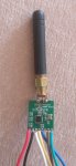
I am trying to use the Teensy 4.0. Code built and uploaded okay. Connected the CC1101 board.

Teensy 3.5 has SPI clock on pin 14. Teensy 4.0 has it on pin 13.

I changed BoardConfig.h so SCK is 13 not 14. I checked the various arduino header files and they correctly have SCK on 13.

When I run the Teensy, the code sends "Initialising CC1101..." and sits there for ever.

I put a scope onto the various pins and see the CS (Chip Select) change. I also see an output square wave from the GDO0 pin (pin 24 on Teensy) presumably in response to the CS. I also see a brief burst of data on Teensy pin 11 (SPI data from Teensy).

However, there is no clock signal on 13 (nor on 14 for that matter- not that I would expect it there). Pin sits at ground.

Now, the internal LED is apparently connected to Pin 13 on the Teensy and the code suggests MicronetToNMEA outputs status of some sort to the LED.

I am wondering if the LED is being signalled by the code and overriding SCK so that nothing comes out?

It appears that the MtN code reassigns SCL from pin 13 to 14 for Teensy 3.x. However, reassignment to alternate pins is not possible on T4.0. So I need to stick with pin 13, make sure outputs to internal LED do not occur and somehow get clock to appear on pin 13!

Any wisdom would be much appreciated as to how I might overcome this. Presumably the info will be useful for others as well. I did try changing pins_Arduino.h for the LED (#define LED_BUILTIN (32)) to move from pin 13 to 32. No change.

Regds,
David
 
Last edited:

doggy

New member
Joined
16 Apr 2022
Messages
11
Visit site
Okay. Progress!
I now have clock out of the T4.0 and data flowing to and from the CC1101.
Clock speed is 4MHz which is good and fine for the CC1101 (max 10MHz).
The code still hangs on "Initialising CC1101..." so now I need to investigate why.
I've put a logic analyser onto the SPI so now I need to decode the data and see what I can figure out.
The SPI protocol for the CC1101 is certainly not trivial to understand.
Regds,
Dave

PS: I changed the internal LED to pin 32 and changed the define for SCK from pin 14 to pin 13.
 

doggy

New member
Joined
16 Apr 2022
Messages
11
Visit site
Success! The final issue was that I had mistyped the RF center frequency so that it was a huge number (thousands of GHz) which caused one of the maths calculations to go into an endless loop and never return. So, now to explore! First impressions are very favourable. For instance, it is detecting the network at 15metres and reports the signal strength as "Very Strong".

I live in a 916MHz area, and here is a spectrum of the network. My centre frequency is 915.91778MHz.
 

Attachments

  • spectrum2.jpg
    spectrum2.jpg
    615 KB · Views: 14

doggy

New member
Joined
16 Apr 2022
Messages
11
Visit site
WOW, A HUGE "Thank you" to Rodemfr, dwarning and those on this forum who have done a lot of measurement and testing.
This is a BRILLIANT project and I find it very exciting.
I have been successfully running my Tweensy 4.0 with a M8N GPS and a magnetometer plus wind transducer, triducer and wind display. Dual display defective on arrival and being fixed/replaced by Raymarine.
CONGRATULATIONS to all!

I have a few basic questions:

1. I note a Tx -> Rx connection from Tweensy to GPS. Does this do anything? Or is it just there for those who want to dynamically configure the GPS? I did not connect it.
2. I am seeing the Hdg and related info on my mn 100-2 display. But I cannot see it in the GPS output to console (option 4). Is it there somewhere in one of the sentences?


Many thanks,
David
 

Jlang

New member
Joined
29 Apr 2022
Messages
4
Visit site
WOW, A HUGE "Thank you" to Rodemfr, dwarning and those on this forum who have done a lot of measurement and testing.
This is a BRILLIANT project and I find it very exciting.
I have been successfully running my Tweensy 4.0 with a M8N GPS and a magnetometer plus wind transducer, triducer and wind display. Dual display defective on arrival and being fixed/replaced by Raymarine.
CONGRATULATIONS to all!

I have a few basic questions:

1. I note a Tx -> Rx connection from Tweensy to GPS. Does this do anything? Or is it just there for those who want to dynamically configure the GPS? I did not connect it.
2. I am seeing the Hdg and related info on my mn 100-2 display. But I cannot see it in the GPS output to console (option 4). Is it there somewhere in one of the sentences?


Many thanks,
David
Hi David,
first: many thanks to Rodemfr, dwarning for this great project.

Question 2: I have a similar or same issue: see further details here: Not all messages where displayed · Issue #4 · Rodemfr/MicronetToNMEA
I have a teensy 4.1 board and first I had only a ublox M8N GPS receiver: my cheap does not store the setting and sends out all nmea messages. As soon as I disabled all messages except GGA and VTG message, I could see SOG,COG and lat/lon on the mn100 display.
Conclusio currently only two message types of the GPS can be displayed (more in github issue)
A simple M8N initialization code can be found in pull request, where you can activate main message types by commenting in/out.
On Teensy 4.1 it is also necessary to reassign SCK pin:
#define SCK_PIN 13
Maybe I am wrong with my assumptions.
 

Jlang

New member
Joined
29 Apr 2022
Messages
4
Visit site
What I forgot: as soon as the compass module is active (connected) no GPS message is shown on the display. The same issue as your question 2.
 

Jlang

New member
Joined
29 Apr 2022
Messages
4
Visit site
WOW, A HUGE "Thank you" to Rodemfr, dwarning and those on this forum who have done a lot of measurement and testing.
This is a BRILLIANT project and I find it very exciting.
I have been successfully running my Tweensy 4.0 with a M8N GPS and a magnetometer plus wind transducer, triducer and wind display. Dual display defective on arrival and being fixed/replaced by Raymarine.
CONGRATULATIONS to all!

I have a few basic questions:

1. I note a Tx -> Rx connection from Tweensy to GPS. Does this do anything? Or is it just there for those who want to dynamically configure the GPS? I did not connect it.
2. I am seeing the Hdg and related info on my mn 100-2 display. But I cannot see it in the GPS output to console (option 4). Is it there somewhere in one of the sentences?


Many thanks,
David
Checked your question 2 again compass and GPS connected:
if I only activate VTG an GGA NMEA message on your ublox module*), then mn100-2 display shows HDG , COG, SOG, lan and lon.

*) I made a commit where you can configure active NMEA message types.
 

doggy

New member
Joined
16 Apr 2022
Messages
11
Visit site
Hello Jlang,
Useful info- thank you.

(a) My question 2 was actually different from what you are saying. I was asking if the compass data (heading) was added to the NMEA output (eg output available via option 4 on the menu). Now I have had a better look, I do not believe the compass data is included in the NMEA stream. Ideally, this would come as a $GxHDG sentence.

(b) You have answered my question 1. I have a non-counterfeit M8N made by Drotek (the French drone people) with a real M8N, proper Flash and an onboard rechargeable button cell. A couple of years ago, I found the real M8Ns were much superior to the cheap ones. I have a lot of options set on my M8N so I really do not need the ability to program it from the Teensy. However, that is still a useful option for those who need it. On my boat, I use the "proper" M8N already and have found it very reliable with better signal strength than the counterfeits, which I have thrown out.

(c) Because my dual digital Raymarine display is being repaired (brand new, faulty on arrival) I only have the wind instrument. It displays HDG properly. It does not display COG but the GPS is only outputting an empty COG field (because it is not moving on my workbench). So I would not expect it to display COG other than as "---". So I do not know whether or not I am seeing the same "bug" as you whereby the various GPS info (COG, SOG, LAT/LON...) are only displayed if there are only VTG and GGA from the GPS. Once I get my dual instrument back I shall check this because I need these things on the wireless display but I also want the full range of NMEA data coming from the GPS. In my systems, I will probably be adding AIS data to the stream.

So, I think being able to restrict the sentences so that the wireless display work is a good interim solution,. ButI think we need to find out why the problem is happening and fix it. If no-one else is able to do this, I can have a look at it when I get my other display.

I sure hope the Raymarine wireless stuff is reliable. As well as the defective display unit, the rod on my wind transducer was improperly drilled in the factory so that if the mounting base is horizontal, the wind vane is tilted 20degrees to the side! As if the boat is permanently listing 20deg to Port! Dreadful quality control from Raymarine.
 

doggy

New member
Joined
16 Apr 2022
Messages
11
Visit site
CC1101 range.

As are a number of people on this forum, I am using one of the cheap CC1101 modules with the solered-on coil/spring antenna. I have tried this soldered so that it is parallel to the PCB but it performs better soldered to be at right angles to the PCB and therefore perpendicular to the ground plane of the board. With that configuration, I can pickup the HDG signal on a display at a maximum distance of 5metres, including one wooden wall.

Further measurements with my spectrum analyser show that the signal strength at a distance of 1 metre is -62dbm. The signal strength at the same distance from a Micronet display is -52dbm. So, the display is about 10dB better than the CC1101/coil-antennna. So it is not surprising to experience worse range from the CC1101 than from a display.

As an experiment, I soldered an SMA connector to the board and added a stubby antenna which is very, very approximately a quarter wave dipole. The impedance match is probably fairly poor. However, the signal strength has improved by 10dB and the range is now 12metres including the same wooden wall. In other words, transmitter performance is now similar to a Micronet display.

Receive performance is similar to the coil/spring setup and so unchanged.

So, for my permanent setup, I'm going to look around for a different CC1101 board with SMA connector and a 915/868 (ISM Band) antenna with a right angle connector.

Edit: I have dug out a half wave 915MHz dipole antenna. So, should be better matched to the CC1101 board. Range has increased further to about 25metres and through the first wooden wall but now as well, 40mm thickness of hardwood floor boards. Both transmit and receive sensitivity have improved further. So, this is more than enough for me. I have ordered several more antennas which are a bit smaller but should still give more than enough range for my sailing boat. I'll just add about 40mm of coax from the board to an external SMA antenna on a small box.
 

Attachments

  • ant.jpg
    ant.jpg
    379.2 KB · Views: 11
Last edited:

Booster

New member
Joined
12 May 2021
Messages
22
Visit site
An update on my esp32 based Micronet to NMEA2000 bridge. I believe it's at a point others should be able to get it working so I'm releasing it. Hope you find it useful.

View attachment 131232View attachment 131233View attachment 131231

esp32Micronet
This project communicates with Tacktick/Raymarine Micronet devices using an ESP32 coupled with a CC1000 or CC1101 radio module. It is capable of sending and receiving data as well as hosting the network or joining as a node. If you add a CAN bus transceiver module it is capable of bridging the Micronet to a NMEA2000 network. Also included is code to read data from an analog AIRMAR ST850-P17 speed transducer and Raymarine masthead wind transducer.

It is rough and needs a lot of testing but functional.

What it does:
• Can use either a CC1000 or CC1101 radio chip.
• Can connect to a Micronet as either a node or host its own network.
• Uses proper window timing for all 4 known network round robins.
• Can send and receive all known data PIDs including node info (it identifies as a type 8 device in settings->health).
• Handles enough command packets to not get booted off the network.
• Handles 0x0A/0x0B device status packets.
• Handles remote shutdown messages.
• Monitors NMEA2k network for PIDs the network can display and forwards them to the Micronet.
• Monitors Micronet for PIDs the NMEA2k network can use and forwards them.
• Can dump packets and monitor other networks.
• Scrolling waypoint names on Dual Displays.

Known issues:
• The CC1101's settings are not completely correct for communicating with the older CC1000 radios. This limits range to about half.
• Settings are hardcoded and should be moved to flash.
• A lot of the N2k < Micronet bridge is untested as I don't have the right equipment.
• There's a few areas in the Micronet class that need to be made thread safe (data structs)
• Tons of fixme's.

You can find it at GitHub - mnsnoop/esp32Micronet.

I made a check with your github code:
Removed the external components transducer and n2kbridge - so only esp32 and cc1101 is connected.
Made the adjustments in radio.h regarding pinning and frequency and set MN_NETWORK_ID0 0x010AC012.
I could upload the code and the program starts with console printout:

0001.013211:INF Starting ESP32 Micronet.
0001.513246:INF Network forced node mode: Listening for a network.

The mn100-2 display is switched on.
Is there a kind of test mode to see the received messages from display.
I think because I have no input from sensors and nmea bridge the program makes nothing:
General asking: Do you see a chance to bring up the m8n module instead the nmea2k sources connected?

But anyway thanks for this great work!
 

tty

Member
Joined
14 Feb 2021
Messages
38
Visit site
All test modes were removed to make the code as simple as possible. Even without input as long as you have the display on it should print the 0x01 sync packets.

I'm guessing your frequency is off. Try setting the esp32 to network choice mode (in micronet.cpp uncommit line 19). When you power on the esp32 it'll listen for a network and when it doesn't find one it'll send out a 4-5 second long preamble to wake up other network devices. Watch for it with your rtlsdr program and tune the frequency setting until it matches your display.

Small correction, MN_NETWORK_ID0 is only the first byte of the network id. You need set:
#define MN_NETWORK_ID0 0x01
#define MN_NETWORK_ID1 0x0A
#define MN_NETWORK_ID2 0xC0
#define MN_NETWORK_ID3 0x12
 

Booster

New member
Joined
12 May 2021
Messages
22
Visit site
Yes with this correction of the ID I found my network.
Your FREQWORD for cc1101 seems to fit my 869.835MHz very well if I observe the 4 seconds preamble with my sdr stick. The power is very high!
Now I got:
Code:
0001.013209:INF Starting ESP32 Micronet.
0001.513241:INF Network choice mode: Listening for a network.
0002.057014:INF Network choice mode: Network detected, switching to node mode.
0002.057127:DBG RX 022 bytes. +000000 μs: (p000000/d+00000) | 01 0A C0 12 | 81 03 70 3F | 01 | 09 00 1A | 14 14 | 81 03 70 3F 08 00 00 3B
0003.056999:DBG RX 022 bytes. +000000 μs: (p000000/d+00000) | 01 0A C0 12 | 81 03 70 3F | 01 | 09 00 1A | 14 14 | 81 03 70 3F 08 00 00 3B
0004.057195:DBG RX 022 bytes. +000000 μs: (p000000/d+00000) | 01 0A C0 12 | 81 03 70 3F | 01 | 09 00 1A | 14 14 | 81 03 70 3F 08 00 00 3B
0004.069358:DBG TX 017 bytes. +013414 μs: (p013359/d+00055) | 01 0A C0 12 | 01 02 03 04 | 03 | 09 00 F3 | 0F 0F | 00 00 00
0005.057001:DBG RX 022 bytes. +000000 μs: (p000000/d+00000) | 01 0A C0 12 | 81 03 70 3F | 01 | 09 00 1A | 14 14 | 81 03 70 3F 08 00 00 3B
0006.057002:DBG RX 022 bytes. +000000 μs: (p000000/d+00000) | 01 0A C0 12 | 81 03 70 3F | 01 | 09 00 1A | 14 14 | 81 03 70 3F 08 00 00 3B
0007.057001:DBG RX 022 bytes. +000000 μs: (p000000/d+00000) | 01 0A C0 12 | 81 03 70 3F | 01 | 09 00 1A | 14 14 | 81 03 70 3F 08 00 00 3B
0008.057101:DBG RX 022 bytes. +000000 μs: (p000000/d+00000) | 01 0A C0 12 | 81 03 70 3F | 01 | 09 00 1A | 14 14 | 81 03 70 3F 08 00 00 3B
0008.069402:DBG TX 017 bytes. +013394 μs: (p013359/d+00035) | 01 0A C0 12 | 01 02 03 04 | 03 | 09 00 F3 | 0F 0F | 00 00 00
0009.057002:DBG RX 022 bytes. +000000 μs: (p000000/d+00000) | 01 0A C0 12 | 81 03 70 3F | 01 | 09 00 1A | 14 14 | 81 03 70 3F 08 00 00 3B
0010.057099:DBG RX 022 bytes. +000000 μs: (p000000/d+00000) | 01 0A C0 12 | 81 03 70 3F | 01 | 09 00 1A | 14 14 | 81 03 70 3F 08 00 00 3B
0010.069439:DBG TX 017 bytes. +013395 μs: (p013359/d+00036) | 01 0A C0 12 | 01 02 03 04 | 03 | 09 00 F3 | 0F 0F | 00 00 00
0011.056998:DBG RX 022 bytes. +000000 μs: (p000000/d+00000) | 01 0A C0 12 | 81 03 70 3F | 01 | 09 00 1A | 14 14 | 81 03 70 3F 08 00 00 3B
0012.057002:DBG RX 022 bytes. +000000 μs: (p000000/d+00000) | 01 0A C0 12 | 81 03 70 3F | 01 | 09 00 1A | 14 14 | 81 03 70 3F 08 00 00 3B
0013.056999:DBG RX 022 bytes. +000000 μs: (p000000/d+00000) | 01 0A C0 12 | 81 03 70 3F | 01 | 09 00 1A | 14 14 | 81 03 70 3F 08 00 00 3B
0014.057101:DBG RX 022 bytes. +000000 μs: (p000000/d+00000) | 01 0A C0 12 | 81 03 70 3F | 01 | 09 00 1A | 14 14 | 81 03 70 3F 08 00 00 3B
0014.069507:DBG TX 017 bytes. +013388 μs: (p013359/d+00029) | 01 0A C0 12 | 01 02 03 04 | 03 | 09 00 F3 | 0F 0F | 00 00 00

Further experiments?
What about to send polled and decoded u-blox messages in the GNSS function?
 

tty

Member
Joined
14 Feb 2021
Messages
38
Visit site
Looks like the display isn't hearing the esp32 properly. It tried 4 times to get a slot with no reply (multiple 0x03 attempts). This can happen if the esp32 is too close to the display or the cc1101's pa power is too high. If you're working with the devices right next to each other try CC1101_PATABLE_N15 or CC1101_PATABLE_N20 for CC1101_POWER (line 35 of radio.h).

You can push data to the micronet at anytime using the following functions of the micronet class:
Code:
    void SetSpeed(float fSpeed);
    void SetTripLog(float fTrip, float fLog);
    void SetWaterTemperature(float fTemp);
    void SetDepth(float fDepth);
    void SetApparentWindSpeed(float fWindSpeed);
    void SetApparentWindDirection(float fWindDir);
    void SetHeading(float fHeading);
    void SetSOGCOG(float fSOG, float fCOG);
    void SetLatLong(float fLat, float fLong);
    void SetBTW(float fBTW);
    void SetWPName(char *cWPName);
    void SetXTE(float fXTE);
    void SetTime(uint8_t iHour, uint8_t iMinute);
    void SetDate(uint8_t iDay, uint8_t iMonth, uint8_t iYear);
    void SetVMG_WP(float fSpeed);
    void SetVolts(float fVolts);
    void SetDTW(float fDistance);
Data is buffered and converted by the functions. Call them at least once a second if you want to keep transmitting that pid. esp32Micronet won't send data over a second old and micronet devices won't display data more than 5 seconds old.

In your GNSS function once you have the cords in decimal degrees call mNet.SetLatLong() with them and you should see 0x02's from the esp32 and the data show up on the display.
 

Booster

New member
Joined
12 May 2021
Messages
22
Visit site
First success:
Inserted static mNet.SetVolts(13.0) into the loop and got it on display.

Code:
0072.704194:DBG TX 020 bytes. +006801 μs: (p006797/d+00004) | 01 0A C0 12 | 01 02 03 04 | 02 | 09 00 F2 | 12 12 | 04 1B 09 00 82 AA
0073.697999:DBG RX 027 bytes. +000000 μs: (p000000/d+00000) | 01 0A C0 12 | 81 03 70 3F | 01 | 09 00 1A | 19 19 | 81 03 70 3F 0D 01 02 03 04 12 00 00 5C
0073.704227:DBG TX 020 bytes. +006819 μs: (p006797/d+00022) | 01 0A C0 12 | 01 02 03 04 | 02 | 09 00 F2 | 12 12 | 04 1B 09 00 82 AA
0074.698015:DBG RX 027 bytes. +000000 μs: (p000000/d+00000) | 01 0A C0 12 | 81 03 70 3F | 01 | 09 00 1A | 19 19 | 81 03 70 3F 0D 01 02 03 04 12 00 00 5C
0074.704249:DBG TX 020 bytes. +006819 μs: (p006797/d+00022) | 01 0A C0 12 | 01 02 03 04 | 02 | 09 00 F2 | 12 12 | 04 1B 09 00 82 AA
0075.698030:DBG RX 027 bytes. +000000 μs: (p000000/d+00000) | 01 0A C0 12 | 81 03 70 3F | 01 | 09 00 1A | 19 19 | 81 03 70 3F 0D 01 02 03 04 12 00 00 5C
0075.704250:DBG TX 020 bytes. +006802 μs: (p006797/d+00005) | 01 0A C0 12 | 01 02 03 04 | 02 | 09 00 F2 | 12 12 | 04 1B 09 00 82 AA

Used your Freqword for 869MHz and PA gain P7 @ 1m distance. Both (display and converter) start-up spectra are near identically with mid frequency 869.839MHz.
Small bug found, for EU band you need a modified PA table:

Code:
//CC1101 PATABLE VALUES - 868MHz
#define CC1101_PATABLE_N30  0x03
#define CC1101_PATABLE_N20  0x17
#define CC1101_PATABLE_N15  0x1D
#define CC1101_PATABLE_N10  0x26
#define CC1101_PATABLE_N6 0x37
#define CC1101_PATABLE_0  0x50
#define CC1101_PATABLE_P5 0x86
#define CC1101_PATABLE_P7 0xCD
#define CC1101_PATABLE_P10  0xC5
#define CC1101_PATABLE_P12  0xC0

I hope there are not other specialties for cc1101 with frequency dependent configurations.

There is, will say, a small anomaly in the settling of the first preamble bytes - see the attached picture.
Bildschirmfoto vom 2022-05-09 18-03-02.png
 

tty

Member
Joined
14 Feb 2021
Messages
38
Visit site
If you're referring to the zero byte before the first preamble byte it's intentional. It's for the CC1000 radio chips but doesn't hurt CC1101's so no point in special casing it out. Good catch on the pa table. I'll update it this weekend. Thanks.
 

Booster

New member
Joined
12 May 2021
Messages
22
Visit site
Yes, this I meant. It doesn't worry for operation - only in URH I have to handle it manually.
I introduced a macro EU in my radio code to switch between the frequencies on certain places.
Code:
#ifdef EU
//CC1101 PATABLE VALUES - 868MHz
#define CC1101_PATABLE_N30  0x03
#define CC1101_PATABLE_N20  0x17
#define CC1101_PATABLE_N15  0x1D
#define CC1101_PATABLE_N10  0x26
#define CC1101_PATABLE_N6 0x37
#define CC1101_PATABLE_0  0x50
#define CC1101_PATABLE_P5 0x86
#define CC1101_PATABLE_P7 0xCD
#define CC1101_PATABLE_P10  0xC5
#define CC1101_PATABLE_P12  0xC0
#else
//CC1101 PATABLE VALUES - 915MHz
#define CC1101_PATABLE_N30  0x03
#define CC1101_PATABLE_N20  0x0E
#define CC1101_PATABLE_N15  0x1E
#define CC1101_PATABLE_N10  0x27
#define CC1101_PATABLE_N6 0x38
#define CC1101_PATABLE_0  0x8E
#define CC1101_PATABLE_P5 0x84
#define CC1101_PATABLE_P7 0xCC
#define CC1101_PATABLE_P10  0xC3
#define CC1101_PATABLE_P11  0xC0
#endif

Another small query: PIN_OP is never used, can be removed in both radio files.
 

Booster

New member
Joined
12 May 2021
Messages
22
Visit site
So, I got it working under Arduino IDE together with u-blox m8n receiver and lsm303dlhc compass. It is a mix of your code (modified) and code from @Rodemfr project. Your SetXXX() functions are wonderful! Tomorrow I will check it together with hull transmitter.
Made a quick check with esp-idf. Build was OK, transmissions starting but no values on display. Maybe some settings (UDP priority, interrupts in IRAM, mutex locks, C++ exceptions etc.) are not compatible.
I can share the code, but didn't know how? PM or your github account as a diff or pull request (never made)?
Thank you.
 

tty

Member
Joined
14 Feb 2021
Messages
38
Visit site
Check what the device is trying to transmit to what is getting transmitted with rtlsdr. My guess is that bit's are being missed because something from the other code is holding an interrupt for too long. Easiest solution is to pin all other code to core 0 so radio.cpp can have core 1 to bitbang to and from the radio. I was doing that for a time but fixed the bad code so it wasn't necessary. It's not the best solution because it leaves core 1 99% idle.

I can add it back in when I get home in a day or two so you can test to see if it fixes the issue.
 

Booster

New member
Joined
12 May 2021
Messages
22
Visit site
Perhaps a misunderstanding. The code arduino compiled works very well, with kull transducer too. I can see depth, speed, lat, long, cog, sog, time, date, heading and other are shown on display. There are a list of small issues. If of interest I can provide this.
Your comment is related to my trial with esp-idf? I only used it for code checking. Should I spent more effort to debug the problem? I have no clue about esp-idf configuration. Which tool you are using?
General question: Which channel we want use for the detailed communication?
 
Top