Raymarine's Micronet

Gixer

Well-known member
Joined
29 Nov 2015
Messages
852
Visit site
Thanks tty.

I've got a bit of a sad story on this...

So the hull transmitter I have is one of the old entry level ones with no internal battery. When checking the connection/heath using the master display I get nothing but dashes. I tried reconnecting it to no avail. My other displays and wind work perfectly.
I managed to find a used hull transmitter with the battery on ebay. This also failed to work but when testing the battery it wouldn't hold any charge. I didn't want to spend £70 on a battery without testing it but had a 9v power supply.... Somewhere in my brain I saw the 3x3v batteries as 9v. You can guess what happened when I connected it up.

So I'm currently trying to get the motivation to spend £300 on a new hull transmitter.
 

tty

Member
Joined
14 Feb 2021
Messages
38
Visit site
So the hull transmitter I have is one of the old entry level ones with no internal battery.

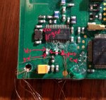
That would mean it's power regulation circuit would be very different from the new ones. Given the transients in a marine starting/charging system I'd instantly suspect it. Did you check for 3.3v at the CC1000/MCU bypass caps?

Somewhere in my brain I saw the 3x3v batteries as 9v. You can guess what happened when I connected it up.
dr-house-relatable.gif
 

Gixer

Well-known member
Joined
29 Nov 2015
Messages
852
Visit site
Thanks again tty,

I really don’t know what I’m doing but have just googled the Bypass capacitor so will have a look and see if I can find it on the board. If I find it and it appears to be the problem can they be replaced?

Dave
 

tty

Member
Joined
14 Feb 2021
Messages
38
Visit site
A bypass capacitor is a capacitor placed between power and ground just before an IC. They're probably not bad but make good test point for the voltage going into the chip. Instead of trying to probe two tiny legs coming from the IC you can touch a probe to both sides of them to see check the voltage.

cc1000bc.jpg

If you don't have ~3.3v measure the resistance across the cap. You should get something in the 10k-50k range. If so then the brains and the radio are probably good and the power supply has failed. You could solder wires to both sides of the bypass cap, inject 3 volts, and try turning on a display. If you get this far triple check polarity, voltage settings and monitor current (It should be basically 0. These chips draw µA's) before/while applying power. The chips are very sensitive and can't handle reverse polarity or voltages over 4v.
 

Gixer

Well-known member
Joined
29 Nov 2015
Messages
852
Visit site
Thank you for the image, I'll bring it home (its still onboard) and bench test the weekend.

Thanks again.
 

WindyWindyWindy

Active member
Joined
5 Feb 2022
Messages
327
Visit site
I'm baffled on this, trying to get a CC1101 working with a PI - so the interrupt driven approach is awkward.
But I'm getting nothing from the instruments. I think my config must be incorrect as I can get junk if I turn down the PQT threshold etc.

I have this:-

Config Registers:
00 IOCFG2 0x2E 01 IOCFG1 0x2E
02 IOCFG0 0x2E 03 FIFOTHR 0x47
04 SYNC1 0x55 05 SYNC0 0x99
06 PKTLEN 0x3C 07 PKTCTRL1 0x80
08 PKTCTRL0 0x00 09 ADDR 0x00
0A CHANNR 0x00 0B FSCTRL1 0x0F
0C FSCTRL0 0x00 0D FREQ2 0x21
0E FREQ1 0x74 0F FREQ0 0x87
10 MDMCFG4 0x6B 11 MDMCFG3 0x83
12 MDMCFG2 0x02 13 MDMCFG1 0x22
14 MDMCFG0 0xF8 15 DEVIATN 0x43
16 MCSM2 0x07 17 MCSM1 0x30
18 MCSM0 0x18 19 FOCCFG 0x1D
1A BSCFG 0x1C 1B AGCCTRL2 0xC7
1C AGCCTRL1 0x00 1D AGCCTRL0 0xB2
1E WOREVT1 0x87 1F WOREVT0 0x6B
20 WORCTRL 0xF8 21 FREND1 0xB6
22 FREND0 0x10 23 FSCAL3 0xEA
24 FSCAL2 0x2A 25 FSCAL1 0x00
26 FSCAL0 0x1F 27 RCCTRL1 0x41
28 RCCTRL0 0x00 29 FSTEST 0x59
2A PTEST 0x7F 2B AGCTEST 0x3F
2C TEST2 0x81 2D TEST1 0x35
2E TEST0 0x09
PaTable:
0x03 0x17 0x1D 0x26 0x50 0x86 0xCD 0xC0

Could someone who's got a working CC1101 dump their config so I can compare?
 

tty

Member
Joined
14 Feb 2021
Messages
38
Visit site
I don't use the same codebase or approach communicating with the radio as the others so my config won't help you. Do you have European or NA micronet kit? What micronet devices do you have? While trying to gather data with the pi did you have a micronet display on?
 

WindyWindyWindy

Active member
Joined
5 Feb 2022
Messages
327
Visit site
The codebase shouldn't matter, it's the CC1101 config registers. I'm on the European version.
Anyway it seems I have to nudge the frequency up very slightly, 0.07 and I get much better reception. So now I'm getting some data out of it at least.

New config:-
Config Registers:
00 IOCFG2 0x2E 01 IOCFG1 0x2E
02 IOCFG0 0x2E 03 FIFOTHR 0x47
04 SYNC1 0x55 05 SYNC0 0x99
06 PKTLEN 0x3C 07 PKTCTRL1 0x80
08 PKTCTRL0 0x00 09 ADDR 0x00
0A CHANNR 0x00 0B FSCTRL1 0x0F
0C FSCTRL0 0x00 0D FREQ2 0x21
0E FREQ1 0x75 0F FREQ0 0x37
10 MDMCFG4 0x6B 11 MDMCFG3 0x83
12 MDMCFG2 0x02 13 MDMCFG1 0x22
14 MDMCFG0 0xF8 15 DEVIATN 0x43
16 MCSM2 0x07 17 MCSM1 0x30
18 MCSM0 0x18 19 FOCCFG 0x1D
1A BSCFG 0x1C 1B AGCCTRL2 0xC7
1C AGCCTRL1 0x00 1D AGCCTRL0 0xB2
1E WOREVT1 0x87 1F WOREVT0 0x6B
20 WORCTRL 0xF8 21 FREND1 0xB6
22 FREND0 0x10 23 FSCAL3 0xEA
24 FSCAL2 0x2A 25 FSCAL1 0x00
26 FSCAL0 0x1F 27 RCCTRL1 0x41
28 RCCTRL0 0x00 29 FSTEST 0x59
2A PTEST 0x7F 2B AGCTEST 0x3F
2C TEST2 0x81 2D TEST1 0x35
2E TEST0 0x09
PaTable:
0x03 0x17 0x1D 0x26 0x50 0x86 0xCD 0xC0
 

tty

Member
Joined
14 Feb 2021
Messages
38
Visit site
Good to hear you've made progress. Here are my settings.

C++:
    ProgramWrite(CC1101_IOCFG1, 0x0B);
    ProgramWrite(CC1101_IOCFG0, 0x0C);
    ProgramWrite(CC1101_PKTCTRL0, 0x12);
    ProgramWrite(CC1101_ADDR, 0x00);
    ProgramWrite(CC1101_CHANNR, 0x00);
    ProgramWrite(CC1101_FSCTRL1, 0x0B);
    ProgramWrite(CC1101_FSCTRL0, 0x00);
    ProgramWrite(CC1101_FREQ2, 0x23);
    ProgramWrite(CC1101_FREQ1, 0x3a);
    ProgramWrite(CC1101_FREQ0, 0x40);
    ProgramWrite(CC1101_MDMCFG4, 0x7B);
    ProgramWrite(CC1101_MDMCFG3, 0x83);
    ProgramWrite(CC1101_MDMCFG2, 0x00);
    ProgramWrite(CC1101_MDMCFG1, 0x22);
    ProgramWrite(CC1101_MDMCFG0, 0xF8);
    ProgramWrite(CC1101_DEVIATN, 0x42);
    ProgramWrite(CC1101_MCSM0, 0x18);
    ProgramWrite(CC1101_FOCCFG, 0x1D);
    ProgramWrite(CC1101_BSCFG, 0x1C);
    ProgramWrite(CC1101_AGCCTRL2, 0xC7);
    ProgramWrite(CC1101_AGCCTRL1, 0x00);
    ProgramWrite(CC1101_AGCCTRL0, 0xB2);
    ProgramWrite(CC1101_FREND0, 0x10);
    ProgramWrite(CC1101_FSCAL3, 0xEA);
    ProgramWrite(CC1101_FSCAL2, 0x2A);
    ProgramWrite(CC1101_FSCAL1, 0x00);
    ProgramWrite(CC1101_FSCAL0, 0x1F);
    ProgramWrite(CC1101_FSTEST, 0x59);
    ProgramWrite(CC1101_TEST2, 0x81);
    ProgramWrite(CC1101_TEST1, 0x35);
    ProgramWrite(CC1101_TEST0, 0x09);

Is the CC1101 module you have a green board with a 2x5 pin header and a small black plastic antenna? The quality of these modules are questionable and I've only had bad luck with them. I'd have to perfectly tune the radio to get a couple feet range. With a good module I can be out of tune over a full deviation and still pick up the network.
 

WindyWindyWindy

Active member
Joined
5 Feb 2022
Messages
327
Visit site
Good to hear you've made progress. Here are my settings.
Thanks.

Is the CC1101 module you have a green board with a 2x5 pin header and a small black plastic antenna? The quality of these modules are questionable and I've only had bad luck with them. I'd have to perfectly tune the radio to get a couple feet range. With a good module I can be out of tune over a full deviation and still pick up the network.
It's one of the cheapo technoiot ones with the spiral antenna. Like these:- TECNOIOT 5pcs CC1101 868MHz Wireless Module Long Distance Transmission with Antenna : Amazon.es: Electrónica
I think maybe the tuning of these things can vary a lot so requires a bit of tweaking for each module.

Our frequency settings seem to be quite different which is odd.

I've only got "analogue" wind to play with, hoping to get true out of the display if I can provide it with SOG & COG.
 

tty

Member
Joined
14 Feb 2021
Messages
38
Visit site
I have NA gear so my frequency is in the 915Mhz band. True wind speed/direction needs apparent wind speed/direction and water speed, not COG/SOG.
 

WindyWindyWindy

Active member
Joined
5 Feb 2022
Messages
327
Visit site
I have NA gear so my frequency is in the 915Mhz band. True wind speed/direction needs apparent wind speed/direction and water speed, not COG/SOG.
Yes, realised that was why the frequency was different.
I only have a wind instrument so it knows the wind.
 

tty

Member
Joined
14 Feb 2021
Messages
38
Visit site
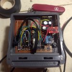
An update on my esp32 based Micronet to NMEA2000 bridge. I believe it's at a point others should be able to get it working so I'm releasing it. Hope you find it useful.

IMG_20220302_215451668.jpgesp32micronetbridge.pngIMG_20220224_231140370.jpg

esp32Micronet
This project communicates with Tacktick/Raymarine Micronet devices using an ESP32 coupled with a CC1000 or CC1101 radio module. It is capable of sending and receiving data as well as hosting the network or joining as a node. If you add a CAN bus transceiver module it is capable of bridging the Micronet to a NMEA2000 network. Also included is code to read data from an analog AIRMAR ST850-P17 speed transducer and Raymarine masthead wind transducer.

It is rough and needs a lot of testing but functional.

What it does:
• Can use either a CC1000 or CC1101 radio chip.
• Can connect to a Micronet as either a node or host its own network.
• Uses proper window timing for all 4 known network round robins.
• Can send and receive all known data PIDs including node info (it identifies as a type 8 device in settings->health).
• Handles enough command packets to not get booted off the network.
• Handles 0x0A/0x0B device status packets.
• Handles remote shutdown messages.
• Monitors NMEA2k network for PIDs the network can display and forwards them to the Micronet.
• Monitors Micronet for PIDs the NMEA2k network can use and forwards them.
• Can dump packets and monitor other networks.
• Scrolling waypoint names on Dual Displays.

Known issues:
• The CC1101's settings are not completely correct for communicating with the older CC1000 radios. This limits range to about half.
• Settings are hardcoded and should be moved to flash.
• A lot of the N2k < Micronet bridge is untested as I don't have the right equipment.
• There's a few areas in the Micronet class that need to be made thread safe (data structs)
• Tons of fixme's.

You can find it at GitHub - mnsnoop/esp32Micronet.
 

mattnj

Well-known member
Joined
26 Jul 2007
Messages
1,350
www.red-data.co.uk
for anyone interested I have made a PCB for this project, with a waterproof box, it includes switching PSU, the compass, CC1101 module, Teensy, bluetooth, WiFi and RS422 nmea interface. I have a few spares available, PM me if interested.IMG_20220314_090315__01.jpg
 

tty

Member
Joined
14 Feb 2021
Messages
38
Visit site
If you are using the antenna that came with the cc1101 module try making a 1/4 wave dipole tuned for your frequency. A software change you could try would be MDMCFG4 = 0x7B. That will decrease the rx filter bandwidth to 232 khz which should give more sensitivity and is the optimum value for 76.8 kbaud, 32 khz deviation, 26 mhz xtal according to RF Studio.

rfstudio.png
 

doggy

New member
Joined
16 Apr 2022
Messages
11
Visit site
I have recently purchased a relatively full set of raymarine Micronet instruments and transducers et al.
So I was DELIGHTED to discover this forum and would like to congratulate all involved in decoding and building stuff. Particularly rodemfr for the well documented GIT project. I have a teensy 4.0 on order plus a cc1101 module and compass.
I was going to port to something else, but easier to spend just a few extra dollars and take advantage of the work already done.
I have been able to compile the code on Arduino Ide.
I installed sloeber (on Ubuntu) because I use Eclipse on some other projects and find it better than arduino-ide.
However, so far I cannot compile the project in sloeber because of compiler paths. Even though I believe I have set them correctly.
I might need to ask some questions if I do not overcome that soon!
Regards,
David
 

doggy

New member
Joined
16 Apr 2022
Messages
11
Visit site
Now compiling okay on Sloeber as well as as Arduino-ide and for teensy 4.0.
Hardware will be another couple of weeks.
I'm really looking forward to testing and trialling and experimenting.
 
Top