Building the Ultrasonic Antifouling Kit from Jaycar

Norman_E

Well-known member
Joined
15 Mar 2005
Messages
24,696
Location
East Sussex.
Visit site
As promised I am posting this thread to describe the build, and hope that others doing so will be helped by it, and post their own hints and tips.

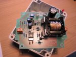
For someone like me, who last dabbled with electonics as a teenager some 50 years ago, modern electronics are witchcraft performed with unfamiliar components. For me the first job is a dry run assembly of the components to the PCB, and the photos below show most of the kit spread out on the work table, with the ready made coil and the trimpot already "planted" on the PCB.

A vital point is the correct identification of the components, and the Jaycar instructions do provide a component list with some identification guidance. Resistors are now tiny things compared to the ones of my youth, and an illuminated magnifier was invaluable in identifying them, as was this website. http://www.diyaudioandvideo.com/Electronics/Color/

I had been puzzled by one resistor which had a gold band in a position where it meant nothing from the Jaycar instructions, because I had looked in the wrong place, (codes brown black black gold brown) but the website revealed that it divided the first three by 10, hence 1 0 0 / 10 = 10 ohms.

tn_IMG_1242.jpg
tn_IMG_1243.jpg
 

Attachments

  • tn_Photo 2.jpg
    tn_Photo 2.jpg
    112 KB · Views: 9
Last edited:

Norman_E

Well-known member
Joined
15 Mar 2005
Messages
24,696
Location
East Sussex.
Visit site
I wrote the above about two hours ago, but forgot the press the "Submit" button.
I have now done the dry run, after some careful research to check correct polarity of various components. I have not put the integrated circuits into their sockets, and one of them is not inserted until the voltage has been regulated, however I an quite puzzled as to which way round they go as each has eight pins in symetrical arrangement, and could easily be put into its socket the wrong way round. Now I have to remove components and start soldering them in one by one.

tn_IMG_1245.jpg
 
Last edited:

Norman_E

Well-known member
Joined
15 Mar 2005
Messages
24,696
Location
East Sussex.
Visit site
Now a question for the electronics wizards here. Should I make sure that components like resistors and capacitors stand a bit clear of the PCB, if so, by how much?
 

elton

Well-known member
Joined
19 Oct 2005
Messages
17,482
Location
Durham, England
www.boatit.co.uk
Brave man!

There will be a notch at one end of the IC, and pin 1 is to the left of it. Otherwise there'll be a dot next to pin 1. The electrolytic capacitors also need to go in the right way around.

I would strongly advise you to practice soldering before you start. Don't overheat the components, especially the semiconductors. If in doubt, grip the component lead with a pair of tweezers to act as a heat sink. The soldered joints should look shiney, not dull grey. Dull grey joints are 'dry joints', and are no use at all. I would strongly advise you to have a solder sucker handy, to correct any mistakes. And use a small (<25W) iron, keeping it shiney and tinned with a damp sponge throughout the job
 
Last edited:

elton

Well-known member
Joined
19 Oct 2005
Messages
17,482
Location
Durham, England
www.boatit.co.uk
Now a question for the electronics wizards here. Should I make sure that components like resistors and capacitors stand a bit clear of the PCB, if so, by how much?
There's no need. High power resistors are often mounted away from the board to aid cooling, but you haven't got that issue.
I sometimes bend the leads of resistors at right angles with pliers to make insertion easier. If you do that, you can easily and neatly mount the resistor a very short distance above the PCB.
 

Norman_E

Well-known member
Joined
15 Mar 2005
Messages
24,696
Location
East Sussex.
Visit site
I bought myself a cheap but surprisingly good 15w soldering iron with a fine pointed tip (plus spares) and am pleasantly surprised how easy it is to get good shiny joints using the solder supplied with the kit. I have so far soldered in the non electronic bits like the fuse holder and connectors.
 

Norman_E

Well-known member
Joined
15 Mar 2005
Messages
24,696
Location
East Sussex.
Visit site
I have soldered all the components to the board, and am giving up for tonight because my neighbour has been given a set of Super Scrabble for Christmas and has challenged me to a game!

Only problem so far is that there are two gold plated pins soldered to the board to connect the switch, but no sockets to fit them are provided. I dont like the idea of just trying to solder the switch wires to the pins. Any ideas? The pins are about the same diameter as motherboard pins in a PC and I am thinking of searching my box of old PC bits to see if I can find a couple of sockets, unless anyone has a better idea.
 

Ubergeekian

Active member
Joined
23 Jun 2004
Messages
9,904
Location
Me: Castle Douglas, SW Scotland. Boats: Kirkcudbri
www.drmegaphone.com
There will be a notch at one end of the IC, and pin 1 is to the left of it. Otherwise there'll be a dot next to pin 1.

There is a notch on the IC sockets too, so all you need do is match the notch on the IC with the notch on the sockets. Assuming that the socket is the right way round, of course ... but that is indicated by the printed symbol on the PCB.

I would strongly advise you to practice soldering before you start.

I used to teach children to solder from scratch, making up a PCB with 42 joints, including one IC socket. I always got them to start with the socket - good practice, very hard to damage.

And use a small (<25W) iron, keeping it shiney and tinned with a damp sponge throughout the job

I used Antex 18W irons, which work fine for this sort of thing. The big problem with a smaller iron is that it heats up everything too slowly - you want to get in, heat up, solder on and out before the components have had a chance to realise what's going on. On a related note, OP, try to use proper leaded solder if you possibly can. Modern tin free stuff is a satanic abomination - it has a significantly higher melting point, so it takes longer to heat, which increases the likelihood of accidents and damage. It also makes worse joints (it's banned in aviation work) and, since it contains copper, eats away soldering iron bit. Foul stuff. Yeugh.
 

William_H

Well-known member
Joined
28 Jul 2003
Messages
13,908
Location
West Australia
Visit site
Lead free solder

I certainly agree it is yuck... I don't recall people having health problems from using lead solder over the last 80 odd years of soldering. olewill
 

Alpha22

Active member
Joined
22 Sep 2003
Messages
1,413
Location
Cambridgeshire
Visit site
I used to teach children to solder from scratch, making up a PCB with 42 joints, including one IC socket. I always got them to start with the socket - good practice, very hard to damage.

An 8Mhz Pic, two motors, 2 kebab skewers, a sheet of plastic cardboard and some mig welding wire by any chance???
 

Norman_E

Well-known member
Joined
15 Mar 2005
Messages
24,696
Location
East Sussex.
Visit site
Does conformal coating make future repairs difficult? I ask because in my youth a friend and I made radio controls for model boats from parts salvaged from old military radio sets. He did most of the building but I stripped the parts from the old sets. When I opened one the works were entirely covered with thick anti fungal "paint" and many of the parts were useless.

I have now made an executive decision, and will not fit the switches, just bridge the terminal posts. The reason is that I do not want anyone turning them off. I will comnnect them to the bilge pump circuit breaker switch on the main panel, via a concealed switch under the chart table, so that I can isolate them, in need.

Next job is to do the internal voltage adjustment. The instructions are a bit unclear in that they say connect a digital multimeter reading DC volts between TP1 and TP0, which is clear enough, but then it just says "apply power and adjust VR1 for a reading of 5V. The question is, do I just connect a charged 12 volt battery, which could be anywhere up to about 13.7 volts, or must I connect an exact 12 volt source?
 
Last edited:

nimbusgb

Active member
Joined
22 Oct 2005
Messages
10,058
Location
A long way from my boat! :(
www.umfundi.com
As I said, when its all tested and complete! :)

It's nothing more than a passive varnish, yes it makes desoldering and sometime resoldering a bit of a pain but not nearly as much of a pain as intermittent faults or early fatality of a circuit through the effects of corrosion.
 

Spuddy

Active member
Joined
8 Jul 2003
Messages
1,957
Location
Kent
Visit site
Norman - most of these ICs can cope with more volts than 12 but worth checking on a data sheet or wait for confirmation from one more clued up than I.
I dislike thread drift but........the PIC controlled buggy sounds just the job to stave off the cabin fever. Any chance of link, please ?
 

elton

Well-known member
Joined
19 Oct 2005
Messages
17,482
Location
Durham, England
www.boatit.co.uk
Next job is to do the internal voltage adjustment. The instructions are a bit unclear in that they say connect a digital multimeter reading DC volts between TP1 and TP0, which is clear enough, but then it just says "apply power and adjust VR1 for a reading of 5V. The question is, do I just connect a charged 12 volt battery, which could be anywhere up to about 13.7 volts, or must I connect an exact 12 volt source?
Do the instructions tell you to adjust it before you insert the ICs? I wonder why it has an adjustment rather than using a fixed 5V regulator.

Anyway I would adjust it using battery power. It's never going to see an exact 12V supply in real life.
 

Ubergeekian

Active member
Joined
23 Jun 2004
Messages
9,904
Location
Me: Castle Douglas, SW Scotland. Boats: Kirkcudbri
www.drmegaphone.com
I dislike thread drift but........the PIC controlled buggy sounds just the job to stave off the cabin fever. Any chance of link, please ?

It's the Brainibot. I'm not sure how easy they are to get hold of nowadays - Rapid used to do the kits but I think i was their main customer. IIRobotics in Edinburgh still list them, at rather more than Rapid used to charge because they re-engineered the drive train a bit.

Peter Balch, who designed them, has a prototype Brainibot II with a much more powerful PIC, IR proximity sensors and a USB link for programming, but nobody has ever ordered enough to make production worthwhile.

If you're interested, PM me and I'll have a look round - I may be able to dig out a PCB and programmed PIC. You'd have to source everything else yourself, though.
 

elton

Well-known member
Joined
19 Oct 2005
Messages
17,482
Location
Durham, England
www.boatit.co.uk
I Googled for studies of the efficacy of ultrasonic antifouling and came across what appears to be the original source of this design, at Silicon Chip magazine. The article includes this interesting warning that caught my eye:

WARNING!
This circuit produces an output voltage of up to 800V peak-peak to drive the ultrasonic transducer and is capable of delivering a severe electric shock.

DO NOT touch the drive unit output terminals, the PC tracks leading to CON2 or the transducer terminals when power is applied.

To ensure safety, the PC board must be housed in the recommended plastic case, while the transducer must be correctly housed and fully encapsulated in resin as described here.

You better make sure you keep it very dry :eek:
 

Alpha22

Active member
Joined
22 Sep 2003
Messages
1,413
Location
Cambridgeshire
Visit site
It's the Brainibot. I'm not sure how easy they are to get hold of nowadays - Rapid used to do the kits but I think i was their main customer. IIRobotics in Edinburgh still list them, at rather more than Rapid used to charge because they re-engineered the drive train a bit.

Peter Balch, who designed them, has a prototype Brainibot II with a much more powerful PIC, IR proximity sensors and a USB link for programming, but nobody has ever ordered enough to make production worthwhile.

If you're interested, PM me and I'll have a look round - I may be able to dig out a PCB and programmed PIC. You'd have to source everything else yourself, though.

Ian, I still build them with kids in Bedford. You may remember me, or my wife Mary. I have had PCBs made and sourced most of the components or replacements with Peters help. Getting the code onto the PIC is becoming the biggest challenge. I may rework the board to take a PICAXE to give it some future. I have had a set of the IR Brainibots, but it wasn't as suitable for kids.

If you have the PIC with code on it then I certainly have a PCB or two to spare. I also have a Rapid parts list for all the components if some one wants a go!!

Sorry for thread drift, I am interested in the Ultrasonic AF kit and will probably indulge if it works out for you.
Deano
 
Top