Building the Ultrasonic Antifouling Kit from Jaycar

superheat6k

Well-known member
Joined
10 Jan 2012
Messages
6,728
Location
South Coast
Visit site
Just been looking at these at SIBS, where I felt £1,500 + vat for a couple of transducers and a small box of electronics was a bit steep for something many seem to be sceptical about.

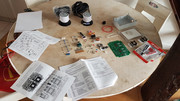
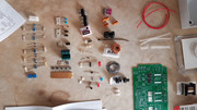
I have read some of this immense thread where extensive mention of the Jaycar unit is made. I see it is self assembly, no issue with that, but to avoid having to trawl through some 372 thread responses can someone point me in the direction of a UK supplier.

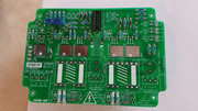
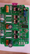
I know they are not the answer to everything fouling but I do like the idea of positioning a transducer above each prop and bombarding them with the noise, because I am simply fed up with the fouling killing boat speed by August each year, and if I can reduce the fouling only on the props I will be quite happy.
 

zambant

Member
Joined
25 Jan 2010
Messages
430
Visit site
I have 2 kits available in the UK - brand new never been opened. PM me if your interested.
I'm in Southampton - can post
Fair winds
John
 

Norman_E

Well-known member
Joined
15 Mar 2005
Messages
24,696
Location
East Sussex.
Visit site
I don't think they will cut fouling on the propellers very much, if at all because they tend to be acoustically insulated from the hull. Ultrasonic antifouling is really about reducing growth on the hull itself.
 

Martin_J

Well-known member
Joined
19 Apr 2006
Messages
4,373
Location
Portsmouth, UK
Visit site
I've not read all the pages of this thread either... Just this one page. :ambivalence:

Regarding prop being isolated from the hull... What are the forums thoughts on attaching one transducer to the top of the saildrive leg (on the gearbox) for example...?

It would surely direct the sound right through the leg then... Perhaps I should just try and see what happens...
 

Martin_J

Well-known member
Joined
19 Apr 2006
Messages
4,373
Location
Portsmouth, UK
Visit site
Ah.

Thinking about it again, the Volvo SD120 leg is isolated electrically from the engine... I'd have to be sure this isolation is maintained .. Can't picture the transducers but isolation shouldn't be too tricky
 

[163233]

...
Joined
13 Jun 2016
Messages
2,382
Visit site
Surely echo sounders pass through the water quite well?

There's a strong whiff of snake oil in anything ultrasound related, imagery aside..
 

ltcom

Well-known member
Joined
27 Mar 2017
Messages
1,202
Visit site
Yep. My opinion has changed. Ultrasound would be much more popular if it worked consistently well.
 

Norman_E

Well-known member
Joined
15 Mar 2005
Messages
24,696
Location
East Sussex.
Visit site
Yep. My opinion has changed. Ultrasound would be much more popular if it worked consistently well.

People often expect too much. Objectively I can say that it does work, but is not 100% effective. Probably a far more powerful system would be needed to keep a boat completely clean, but on haul out it was easy to see on my boat that the cleanest areas were the ones close to transducers and that there was more fouling, which was generally close to the waterline, further away. The system did allow me to haul out and antifoul the boat every two years instead of every year. In that alone it paid for itself.
 

jiris

Member
Joined
13 Oct 2014
Messages
364
Location
Australia
Visit site
I don't think they will cut fouling on the propellers very much, if at all because they tend to be acoustically insulated from the hull. Ultrasonic antifouling is really about reducing growth on the hull itself.

I beg to differ. I installed UA about 10 months ago and I am amazed by its performance. Especially the prop is sparkling clean - see the pic - about 5 months of it was in tropical waters, the shiny spots are bare metal where the antifouling peeled off after a few weeks form application. The rest of the hull has only a few lone strands of seaweed, the only thin layer of barnacles are - for some reason on the skeg (visible). The growth DSCF2366.JPGslowed down dramatically even on the dinghy behind the boat.
 

Peuwi

New member
Joined
13 Mar 2019
Messages
2
Visit site
Great thread and thanks to all positive contributions. I just took delivery of the Mk 2 version and never realised how much assembly was required.
Is there anyone else putting one of these together as seems quite different from the original pics from thread starter Norman_E?

Cheers and Beers.

Hello,
I made the assembly of the version II of the jaycar kit.
I guess this will be too late for you, but this thread was interesting for me, so I'll contribute with my own inputs.

Full content of set (keep in mind that I have 2 transducers kit : 1x KC5535 + 1x KC5536)

Everything (but the tools hidden behind paper) on the table is provided

Zoom on component : sorted by the order of the inventory (since we can wonder what is what)

Nota : I put screw directly on mofset

Assembly : first step. (there is a mistake, variable resistor are to be installed way after)


Assembly : second step. (for the first 2 steps, just keep in mind you'll have to solder every small component by order of thickness


Assembly : third step, ready for testing !

(for people like me, doing the assembly at home, and wondering how to test : I just used a pc power supply : the black is 0V, and the yellow is 12V DC.


Tools required :
-> multi-meter
-> soldering iron
-> a set of small screwdriver
-> something to cull large hole in plastic : I used a conic reamer for wood. Worked fine and clean with very low rotation speed.
-> patience, and 10+ hours (maybe less if you are used to such assembly, and/or ready to skip regular checks)
-> ~12V / 1A power supply for testing

Additional component required :
1mm² 2 cables electric wire for power supply. Length up to you.
 

Norman_E

Well-known member
Joined
15 Mar 2005
Messages
24,696
Location
East Sussex.
Visit site
Peuwi, Welcome to the forums.

Unfortunately the images you have linked are far too big and I cannot see any of them. May I suggest you resize them and post them on here. I use a free program called Easy Thumbnails, available here https://www.fookes.com/easy-thumbnails to resize pictures for posting. 800 x 600 is fine and nothing bigger than 1200 x 900 is needed.

EDIT: I now see the pictures!
This is quite different from the ones I built back in 2010. I presume this model designed to drive two transducers from a single unit? I remember that I had to have the coil installed but not the main IC before I could set the voltage when I built mine.
 
Last edited:

Peuwi

New member
Joined
13 Mar 2019
Messages
2
Visit site
Yep, sorry, I didnt expect for my post to be reviewed before online, so I couldnt check it myself and make sure pictures are fine.
If some moderator resized thumbnails himself, thanks to him :)

Yes, this is the version II of the jaycar kit. It allows to get 2 transducers on a single unit.
So, yes, this kit is supposed to be simpler, especially for transducers. Also, they are a bit more powerful (with higher consumption coming along).
Nota : they are not synchronized, they doesnt work together. More precisely, they are synchronized, but they are only working at their turn, not simultaneously.
 

JohnMath

New member
Joined
11 Jul 2021
Messages
2
Visit site
Some Jaycar ultrasonic antifouling kits blow the power fuse. Here is the reason why:

The circuit has two Schotky diodes D1 & D2 from the FET gates to the +5volt rail to protect the outputs of IC2 from voltage spikes. If you look up the specification these 1N5819 diodes can have a reverse leakage current up to 1mA, although I measured a little less than 1µA for the two supplied in my kit. The FETs have a turn on voltage of something over 2 volts. In some cases at turn on the leakage current from the Schotky diode is enough to turn one one or both FETs before IC2 starts running. The FET(s) thus turned on short circuit the power supply through the transformer and the fuse blows.

My fix was to install 390kΩ resistors from the gate of each FET to ground. That stops the leakage current from the Schotky diode from building up enough voltage to turn on a FET by limiting the voltage to V=I*R = 0.000001 x 390,000 = 0.39volts, which is well below the gate turn on voltage. When the circuit is running these resistors effectively sit there doing nothing.
 
Top