Petertheking1982
Well-Known Member
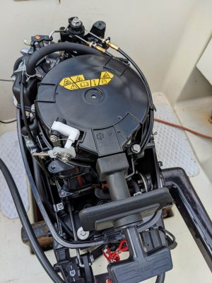
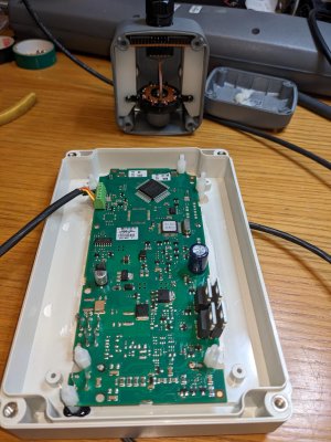
I had an st2000 on an achile's 24 with motor in well directly under the tiller. It would be fine if motor off, but went haywire if the motor was running. I ended up going the external compass route (if your brave / skint you can remove internal compass and solder on extension lead!). I think main problem with my motor was the magneto charging coil which was a big ring of magnets on top of the engine.