vas
Well-Known Member
hello all,
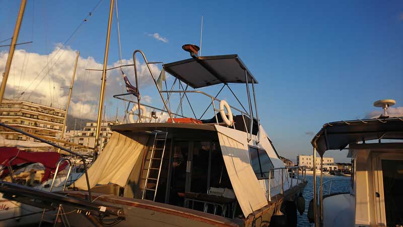
managed to do some work on the Hard Top so a report is well overdue.
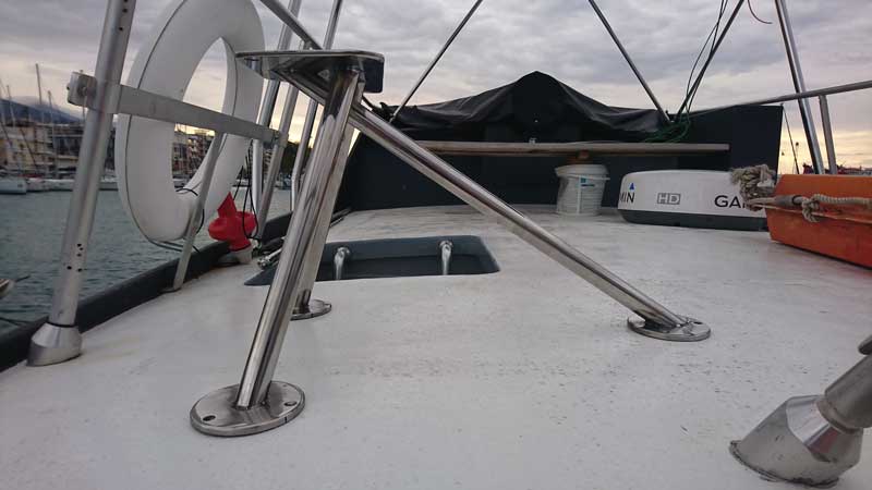
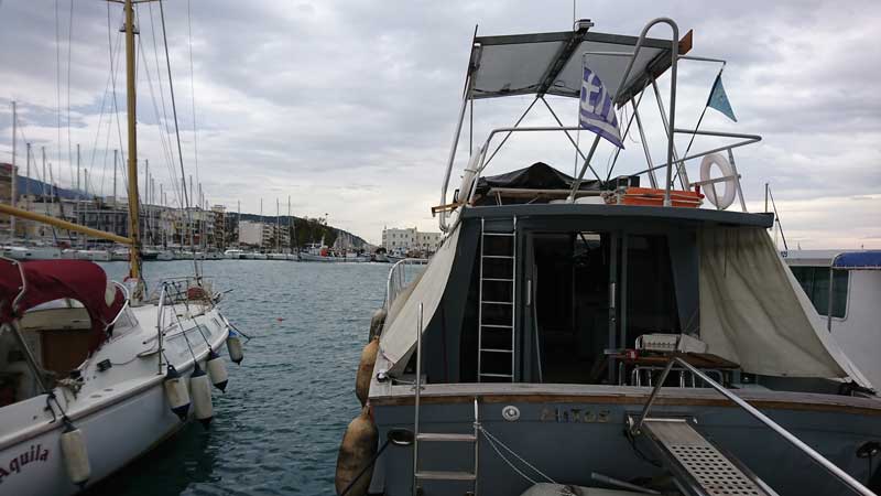
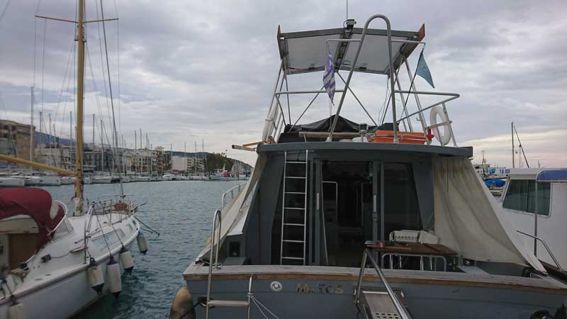
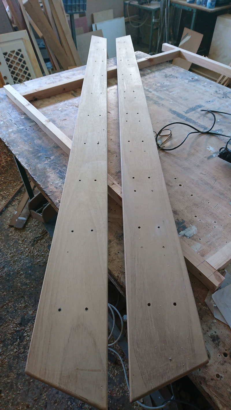
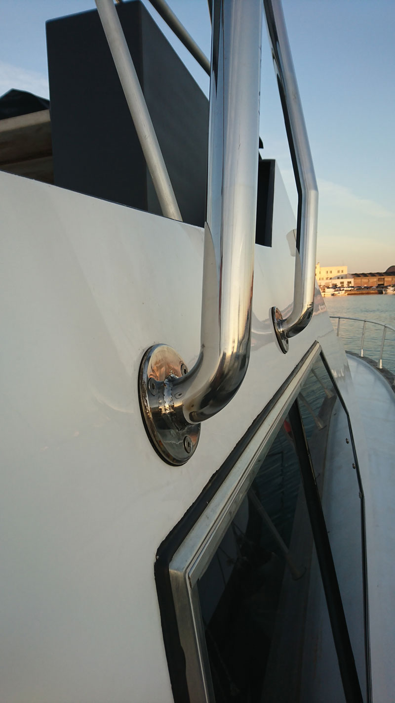
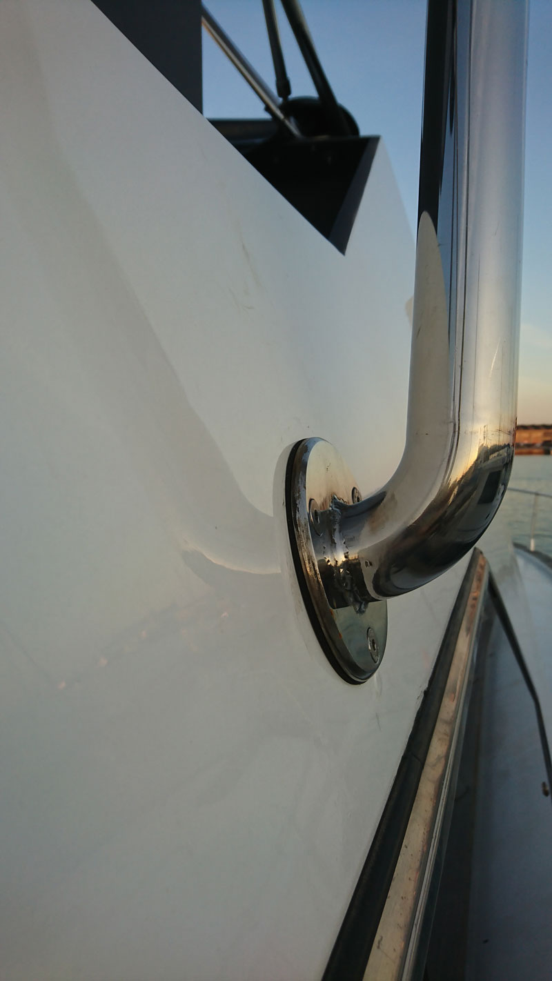
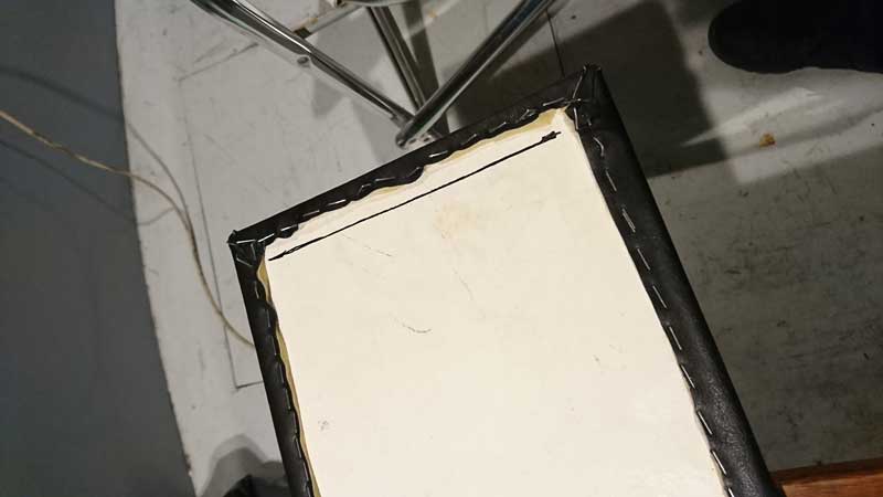
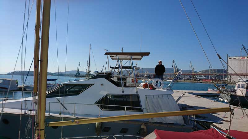
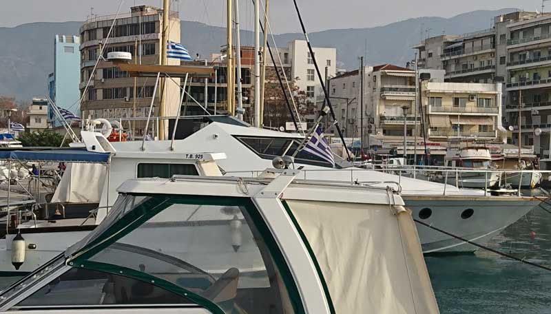
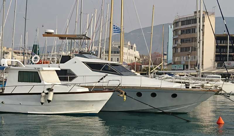
To start with, the following two pics are the stbrd side of the h/t columns/pillars, corrected and refitted with a 3mm rubber flange.
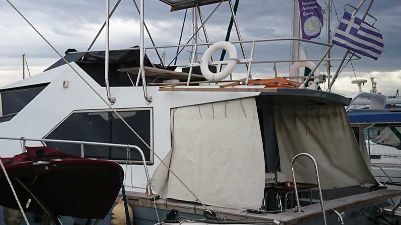
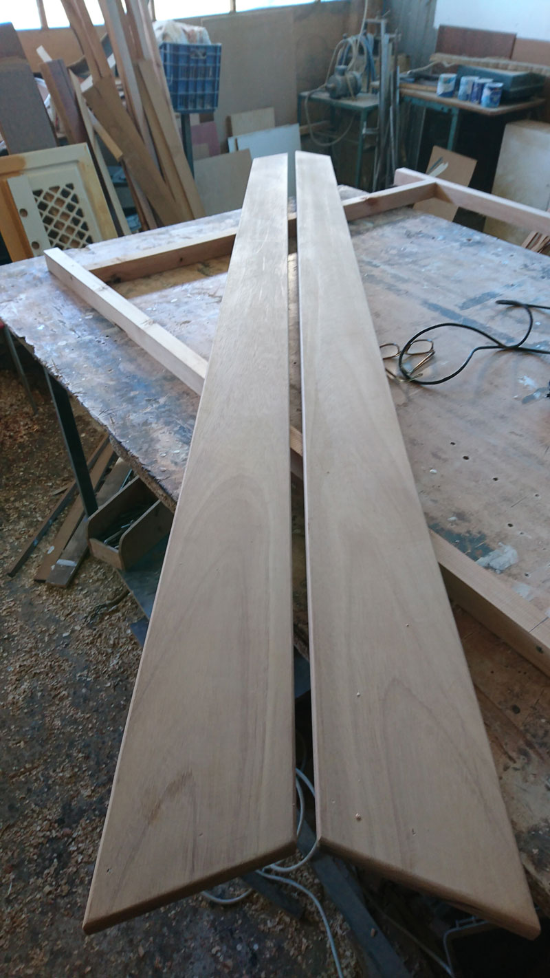
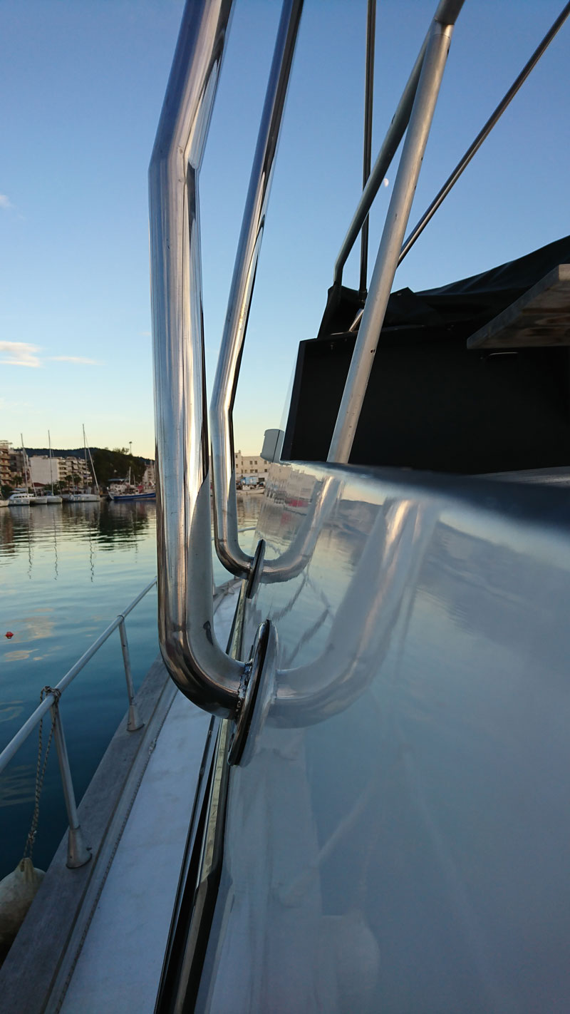
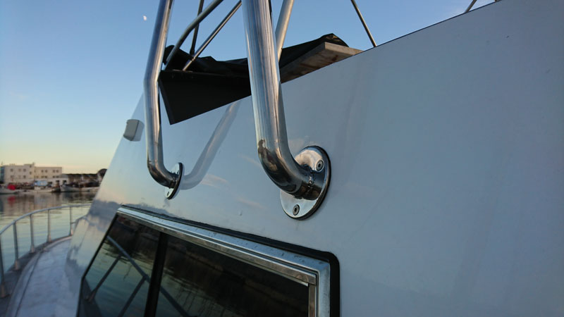
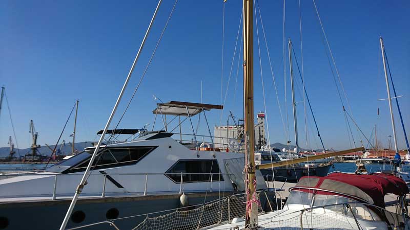
and the following two are the port side done a couple of weeks ago:
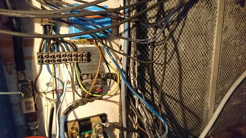
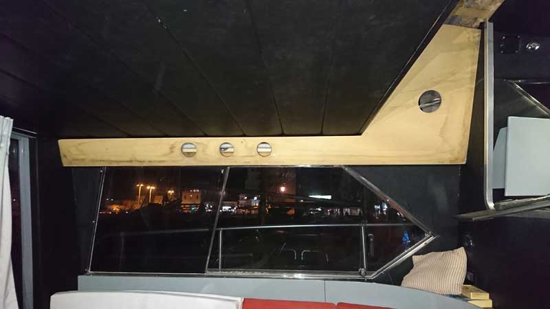
Now, as part of this disruption (cables that had to be unrouted through the 48mm pipes) it was the right time to do a precautionary reinforcement of the superstructure in the area. Superstructure is 12mm marine ply, under the pillar flanges is the side window frames (extremely robust cold formed sections of at least 2.5mm SS. On top of the flanges is the joint between sides and f/b floor with decent reinforcement with iroko beams. So all that was beefed up with another 12mm marine ply (approx 100X1700mm) epoxied on the existing one going from the top iroko reinforcement all the way to the small cross beam that supports the side upholstery panel - you've not seen that yet in place as it was one of the first MASSIVE pieces of ply removed for the rebuilt and for the last 6yrs is in George's workshop...
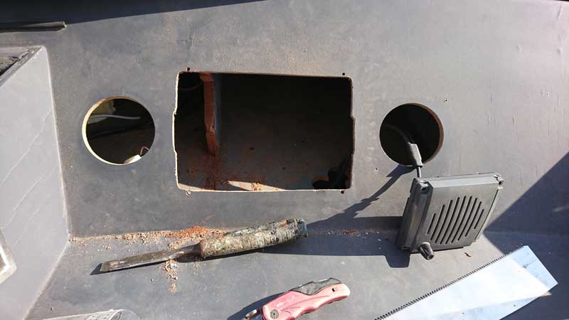
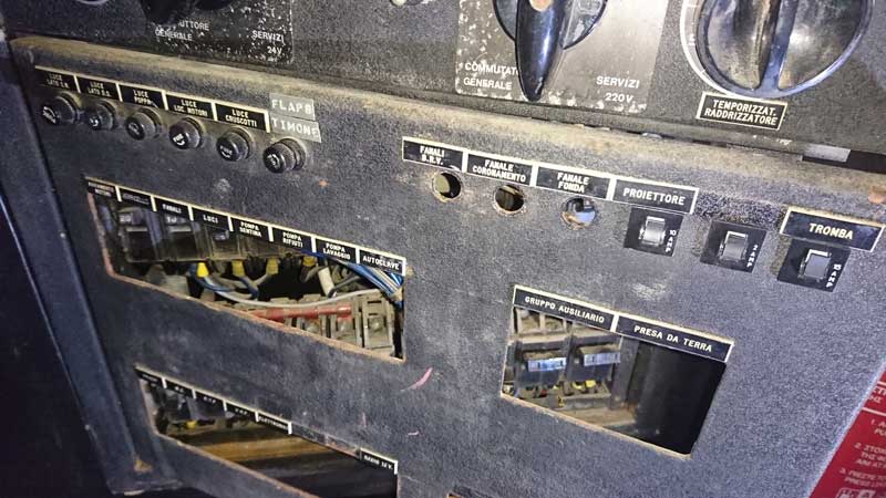
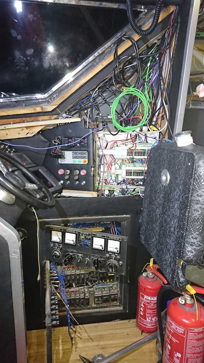
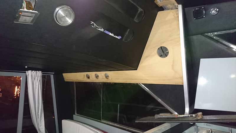
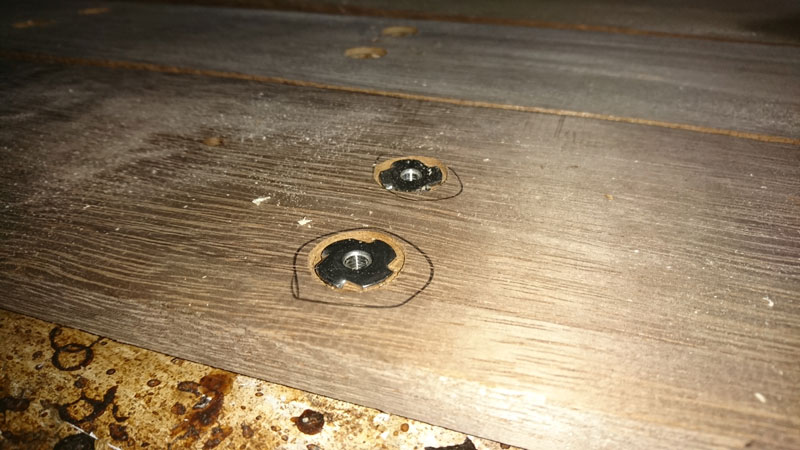
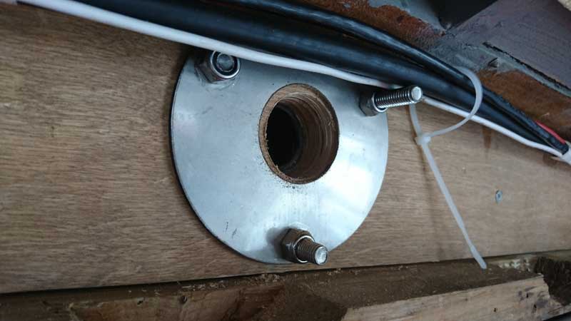
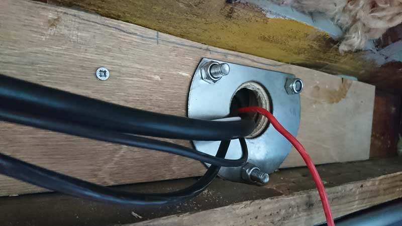
Stbrd side was trickier as flanges and columns were in place so I had to carefully undo push the screws back, match, test fit, drill the hole for the radar, wind and anchor nav light, thread the cables through, epoxy and bolt the lot in place. All that without making a mess to lacquered furniture and other things around... Happy to report that all went v.well:
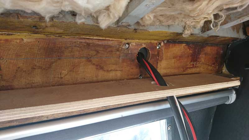
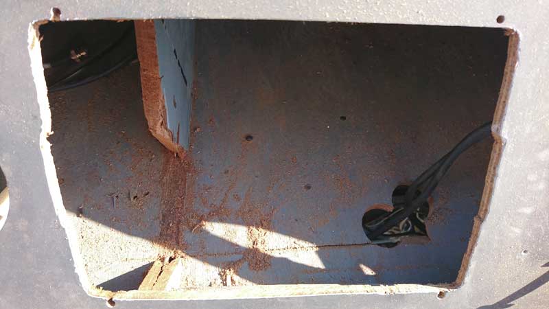
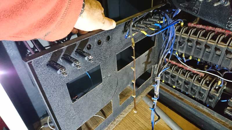
loose tie wraps just in case a new wire has to go through:
Next step and the day Nikos had the port side for corrections to the flanges, I did that side on a blank sheet so to speak, nothing to mess with, just getting the shape right and epoxying. Much easier so once the columns were back in place it was an easy job to complete, bolt, level and finish it:
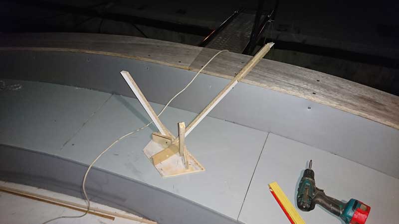
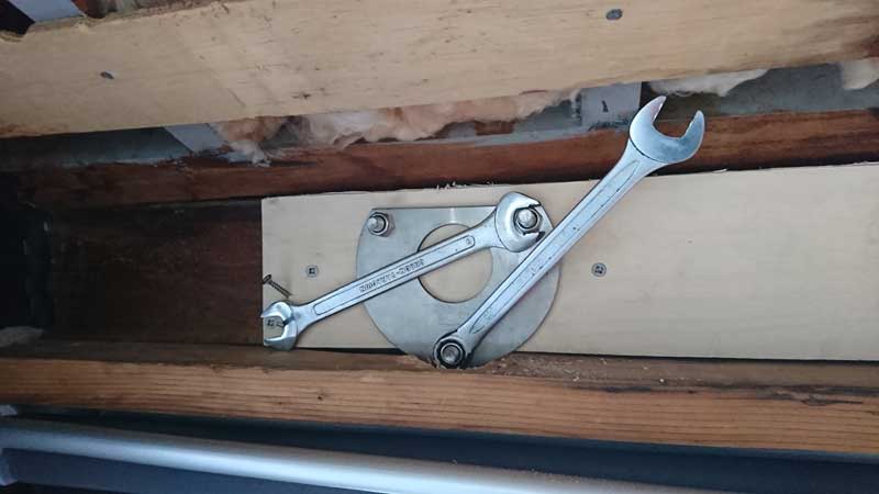
working alone meant I had to devise various (silly) methods to keep the nut in place while bolting from outside, front flanges were fine as with the window slide back I could reach with my hand from the outside, rear though no chance unless you had 1.5m long arms (at least...):
Initial placement of the h/t flanges was slightly off, and wasn't sloping to aft to empty rainwater. Actually, it was ever so slightly slopping to the bow (where the gutter is blocked...). Turns out that normal boat movement does empty the gutters anyway, but I lowered the aft flanges placement by 10mm and got the gutters level.
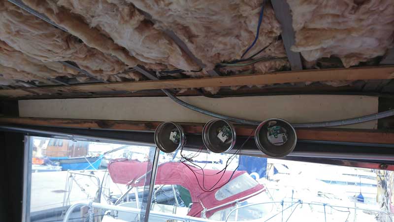
Furthermore, following this reinforcement, it was clear that the ceiling slats wouldn't fit and they ALL needed 10-30mm shortening (on EACH side!), nice... Remember that slats are pushed up and slide to stbrd in order to "hook up" with the thin strips of ply bolted on the ceiling beams.
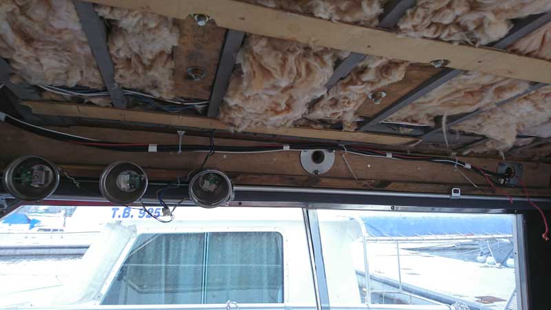
Was easier than I thought, finished it all in an evening. Now all slats are in place and there's enough space for cables, conduits, lights, you name it:
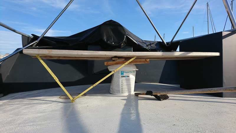
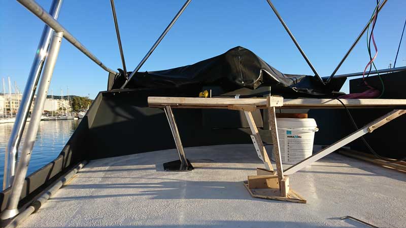
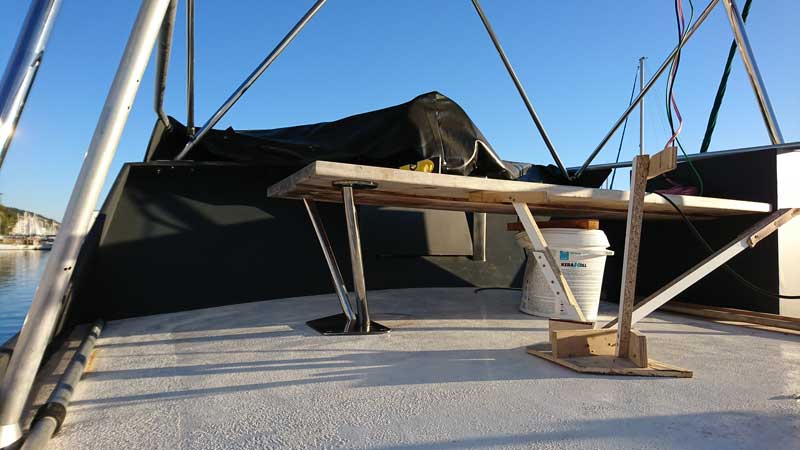
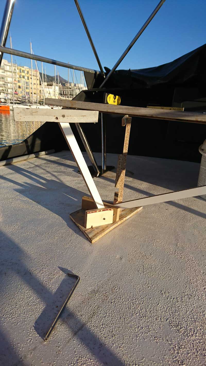
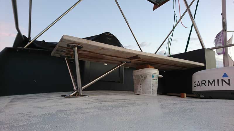
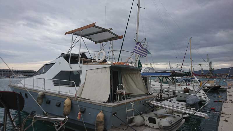
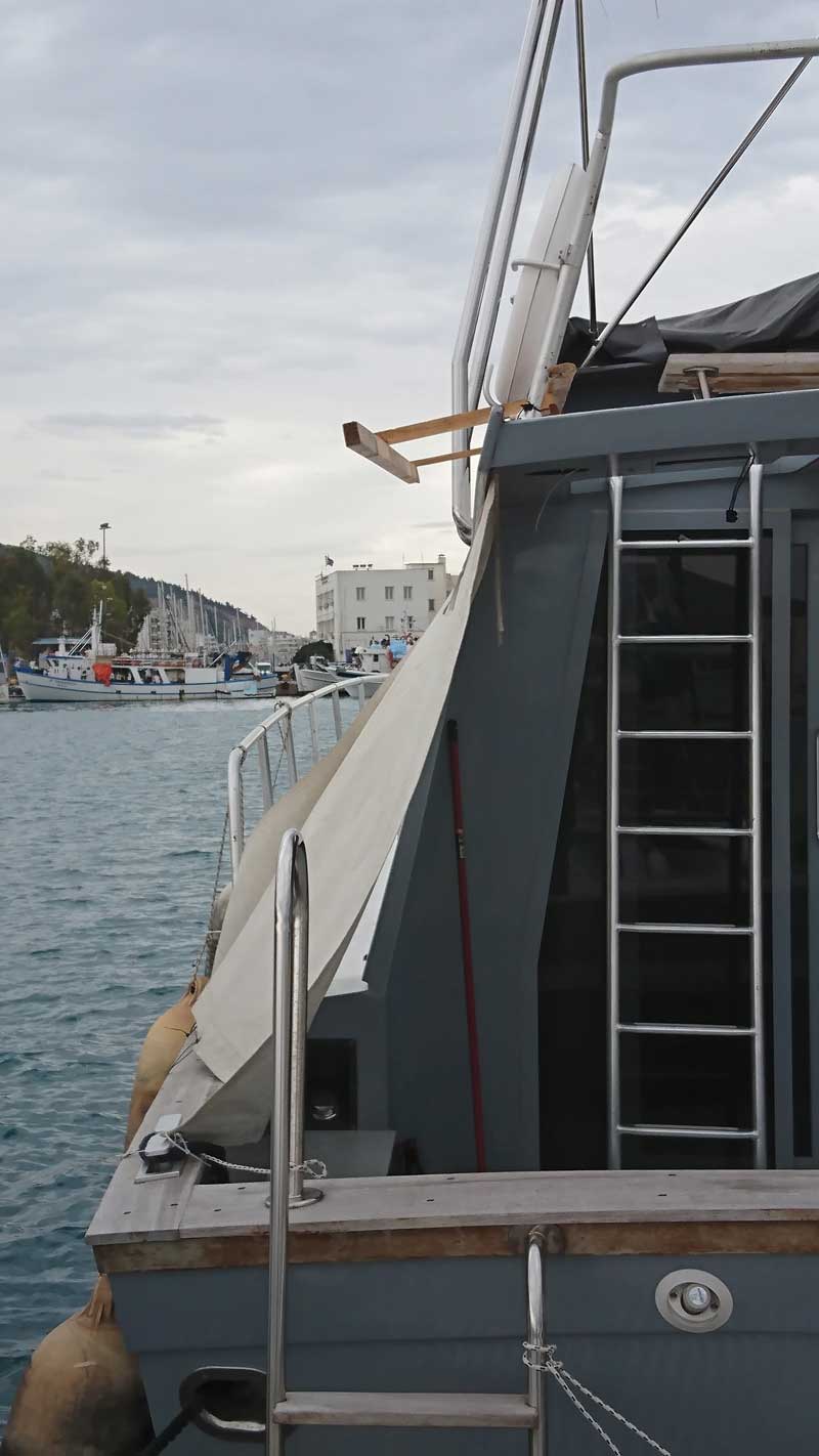
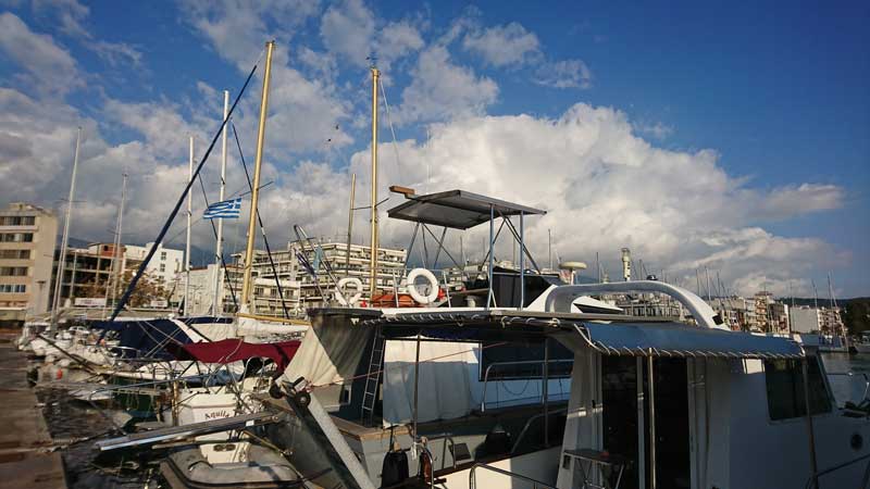
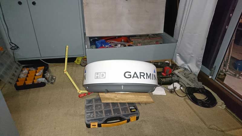
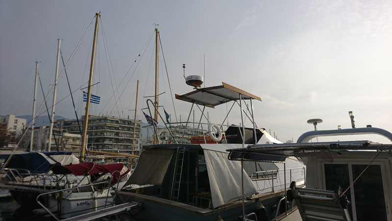
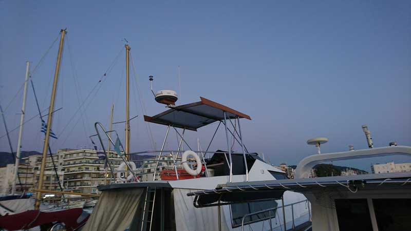
I have mentioned fitting two iroko side skirts to the h/t, well this was attempt at getting the first one in place and balancing taper as well as fore-aft and up-down placement. Looked fine at the time, George made an exact copy for the stbrd side and they are both test fitted now (not on the following pics though). Doesn't look too bad tbh, wasn't sure on the fore-aft placement, adding the radar on yesterday, proved that they are indeed to far aft, so got to alter placement and move them forward by at least 80mm. We shall see, not in a hurry, got to make sure I like it first
The one part of the h/t that I've only sketched v.roughly are the shading slats on the front over the wheel and dash which are again going to alter the balance of the thing. So need to be careful not to loose it.
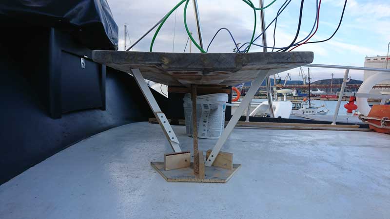
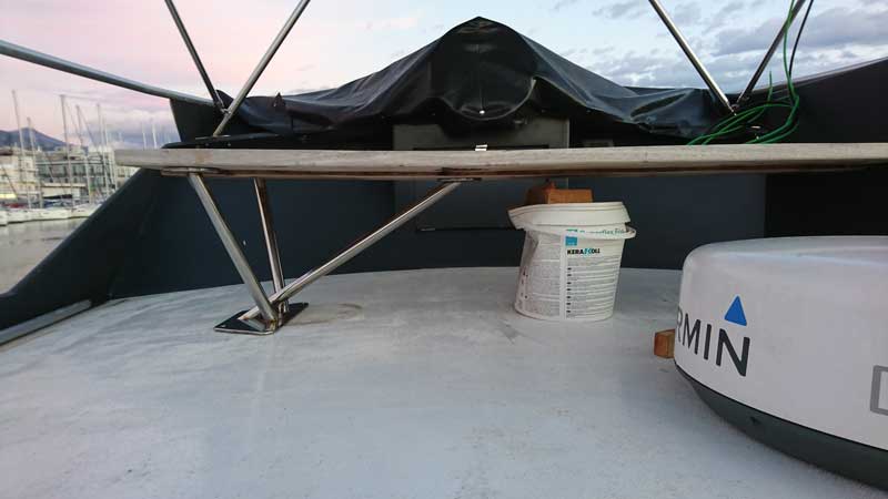
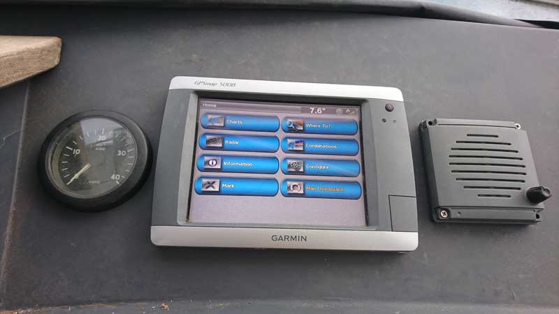
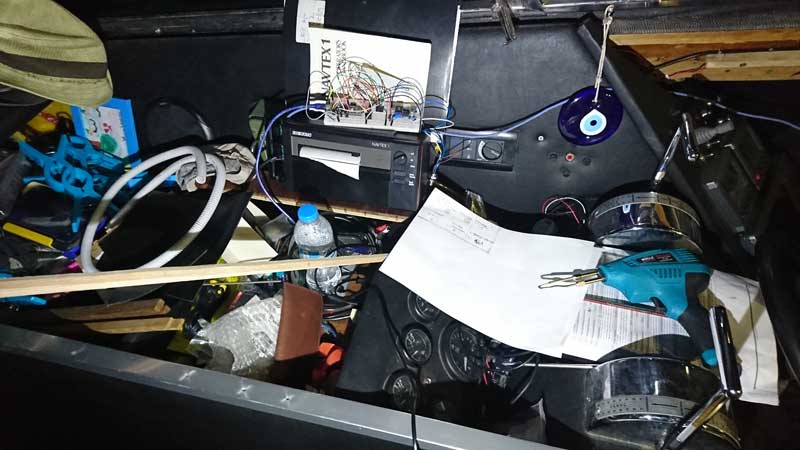
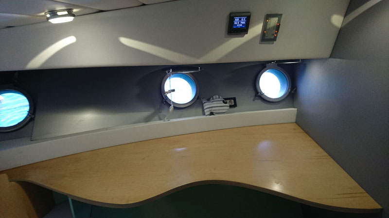
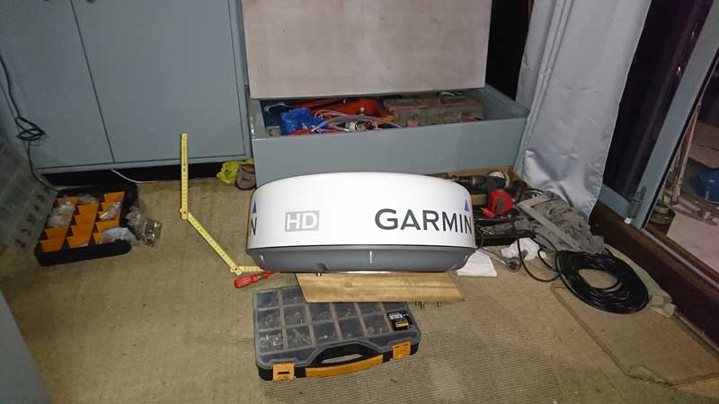
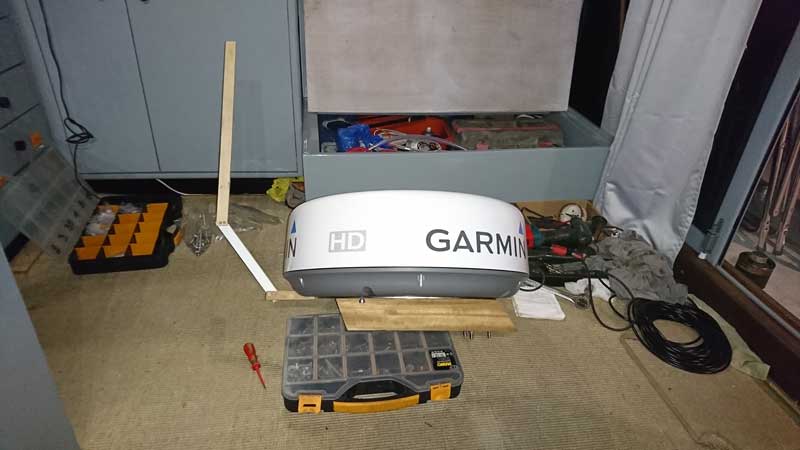
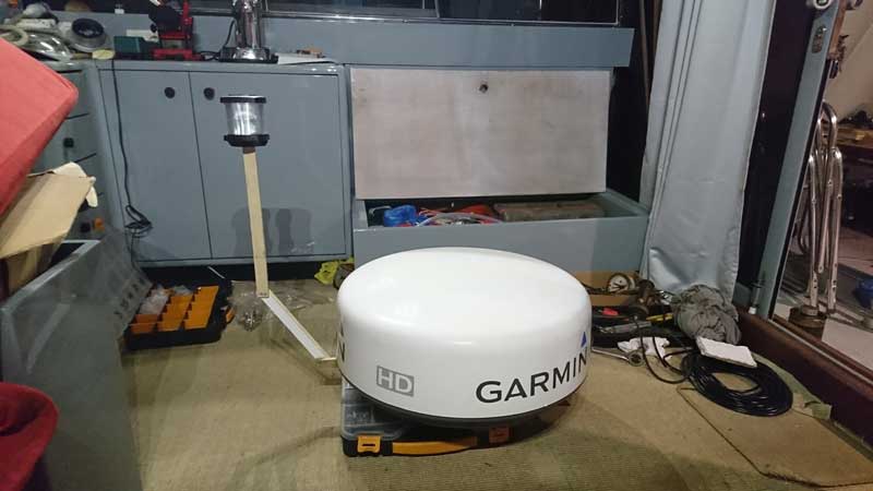
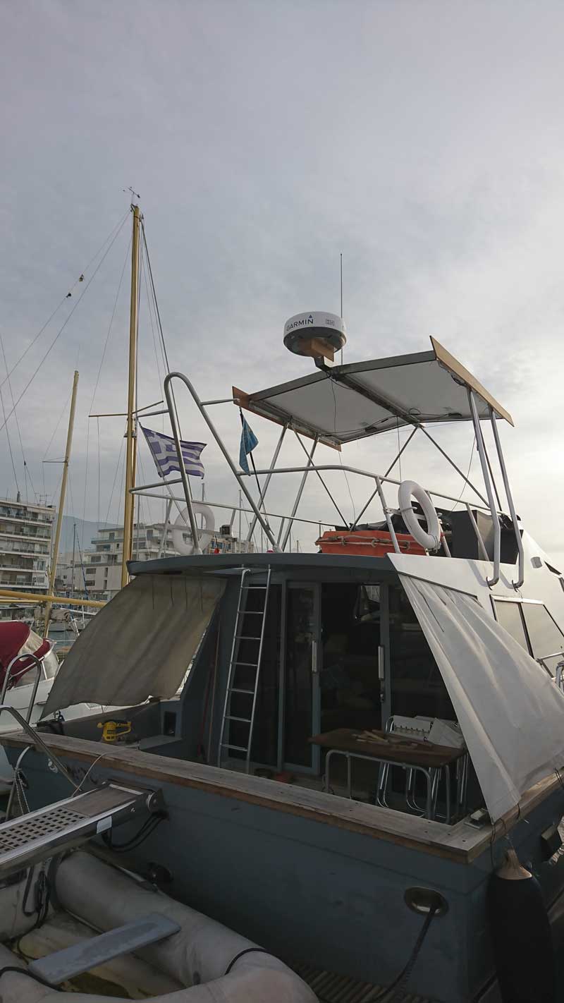
I have mentioned programming for the NASA wind instrument I don't think it's visible on any pics up to now, so that's were it's sitting now, works a treat, may actually lift it by 15mm or so with new support plate under the central section of the h/t:
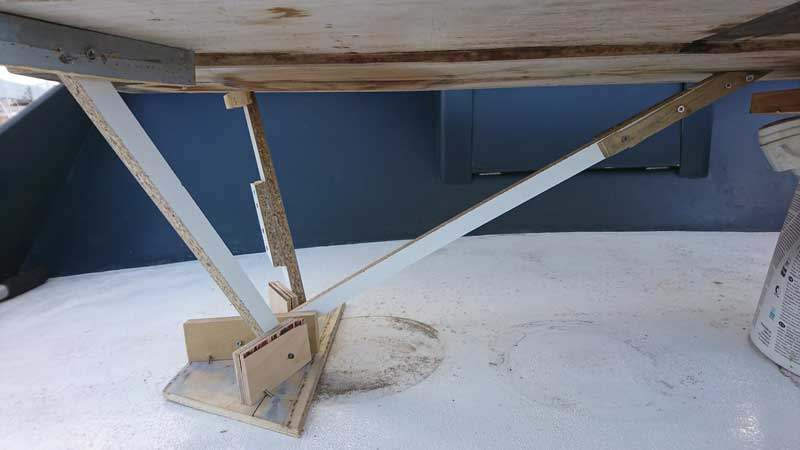
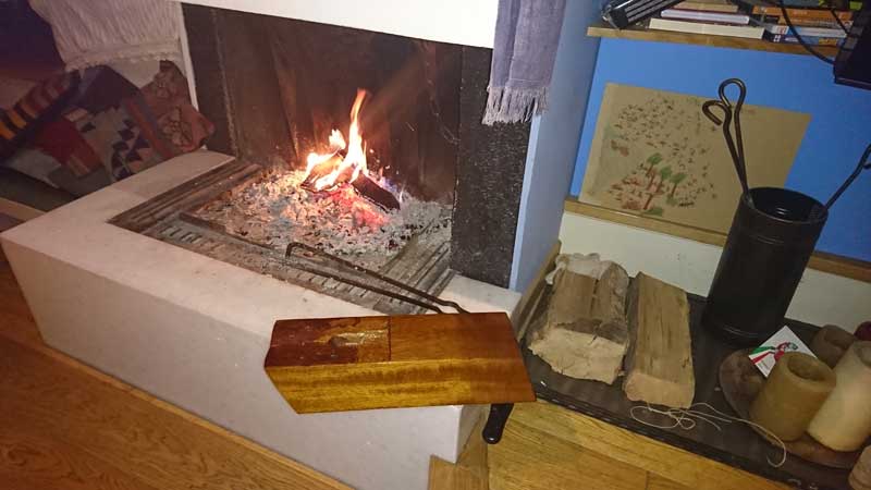
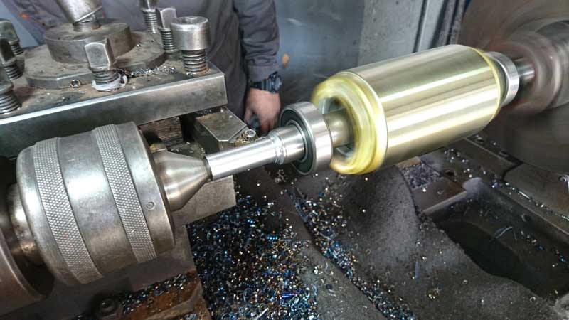
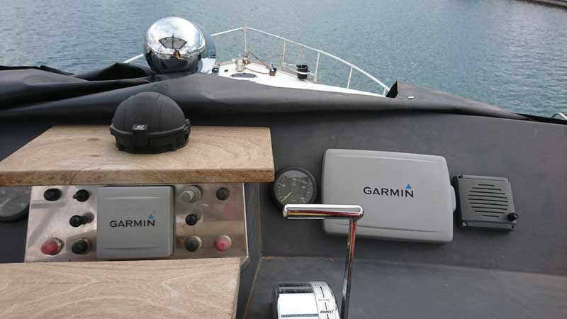
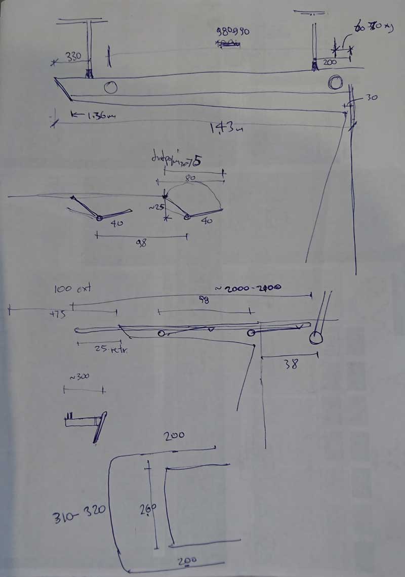
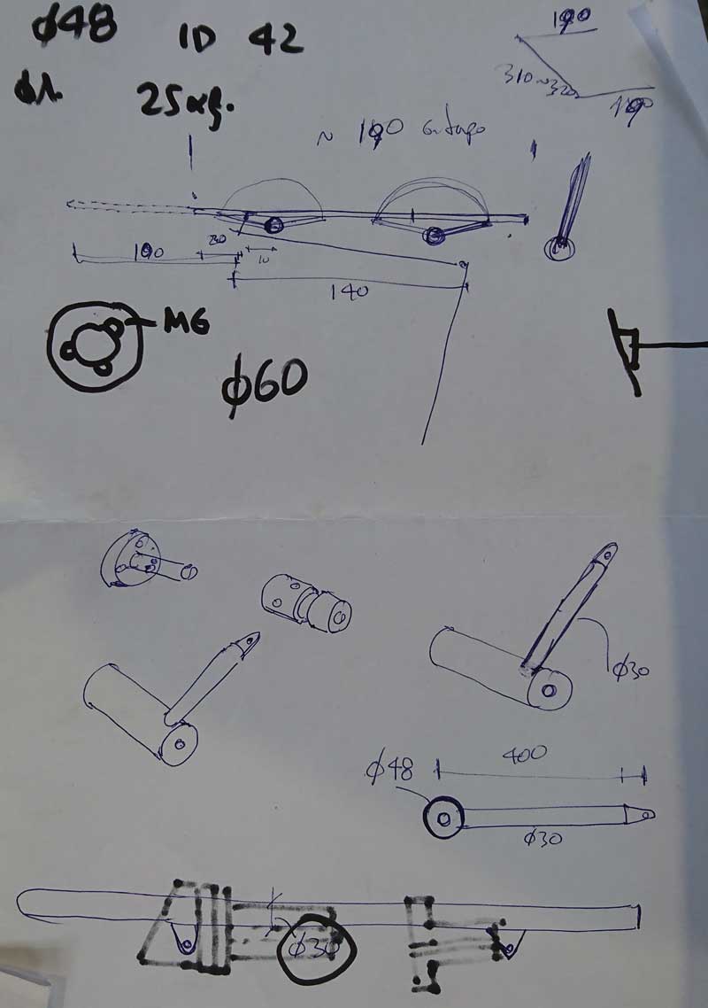
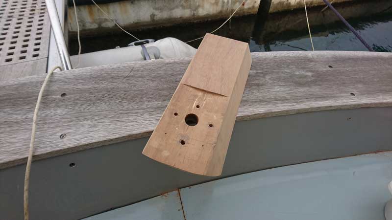
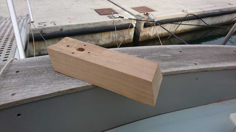
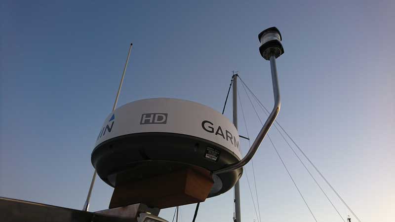
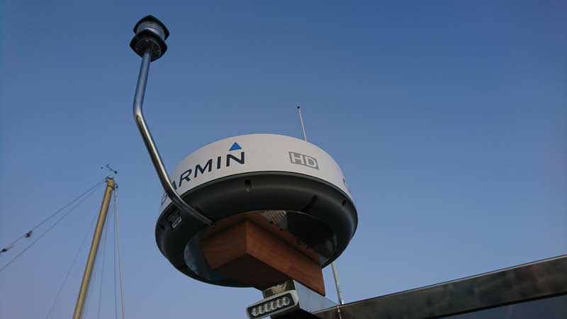
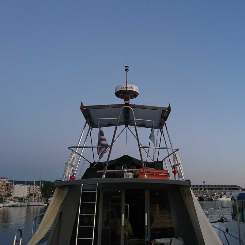
This is the solid iroko beam on which the radar ss plate (and the radar on top of it) sits/bolts. IT was funny as this piece was the left overs of the beam that George bought for the side skirts to the h/t. OK, I asked him to buy a piece 300-350mm longer so we use that, but turned out a massive piece and very solid. After a bit of carving (top of the central beam of the h/t is not flat but has a 3-4degree slope on each side) and a fair amount of work drilling 3mm & 5mm ss on the spot (and over your head with the hot grinds on your hair and arms, v.nice...)
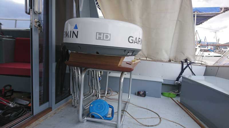
Final pics for the day, beam and the 5mm ss plate in place:
waiting for Nikos to fabricate the anchor navlight pole and I'll report the final instalment of the radar placement.
Then I'll need to decide on the construction and fabrication of the shading slats as well as the upholstery for the "ceiling" of the h/t and placement of lights/speakers/sensors, et al up there.
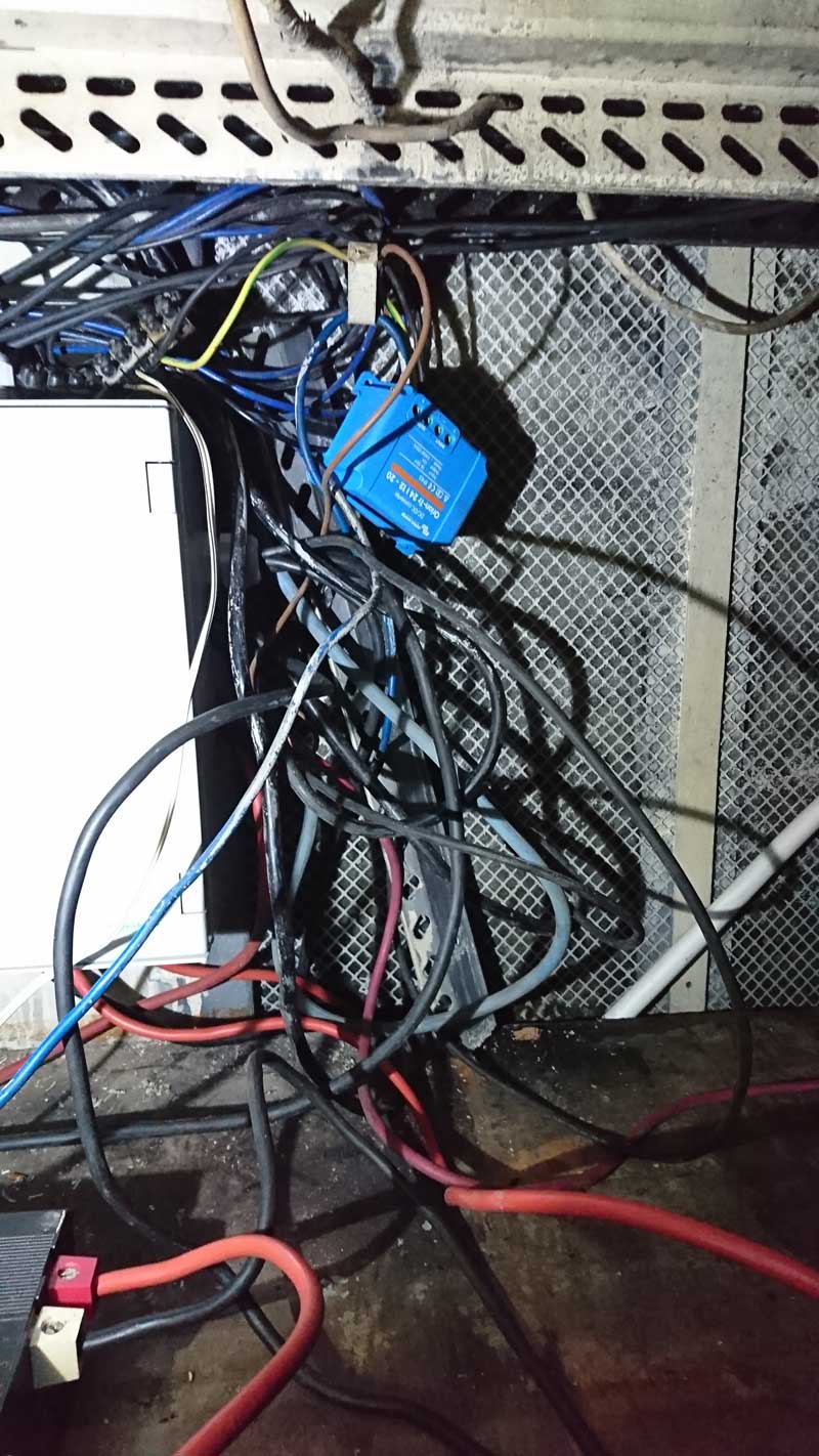
I've gone overboard with wiring the h/t pretty sure half the cables will be "just in case" but not so keen on stripping half the boat for adding them at a later date...
cheers
V.
managed to do some work on the Hard Top so a report is well overdue.
To start with, the following two pics are the stbrd side of the h/t columns/pillars, corrected and refitted with a 3mm rubber flange.
and the following two are the port side done a couple of weeks ago:
Now, as part of this disruption (cables that had to be unrouted through the 48mm pipes) it was the right time to do a precautionary reinforcement of the superstructure in the area. Superstructure is 12mm marine ply, under the pillar flanges is the side window frames (extremely robust cold formed sections of at least 2.5mm SS. On top of the flanges is the joint between sides and f/b floor with decent reinforcement with iroko beams. So all that was beefed up with another 12mm marine ply (approx 100X1700mm) epoxied on the existing one going from the top iroko reinforcement all the way to the small cross beam that supports the side upholstery panel - you've not seen that yet in place as it was one of the first MASSIVE pieces of ply removed for the rebuilt and for the last 6yrs is in George's workshop...
Stbrd side was trickier as flanges and columns were in place so I had to carefully undo push the screws back, match, test fit, drill the hole for the radar, wind and anchor nav light, thread the cables through, epoxy and bolt the lot in place. All that without making a mess to lacquered furniture and other things around... Happy to report that all went v.well:
loose tie wraps just in case a new wire has to go through:
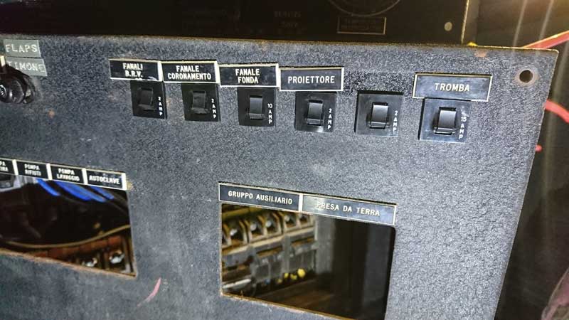
Next step and the day Nikos had the port side for corrections to the flanges, I did that side on a blank sheet so to speak, nothing to mess with, just getting the shape right and epoxying. Much easier so once the columns were back in place it was an easy job to complete, bolt, level and finish it:
working alone meant I had to devise various (silly) methods to keep the nut in place while bolting from outside, front flanges were fine as with the window slide back I could reach with my hand from the outside, rear though no chance unless you had 1.5m long arms (at least...):
Initial placement of the h/t flanges was slightly off, and wasn't sloping to aft to empty rainwater. Actually, it was ever so slightly slopping to the bow (where the gutter is blocked...). Turns out that normal boat movement does empty the gutters anyway, but I lowered the aft flanges placement by 10mm and got the gutters level.
Furthermore, following this reinforcement, it was clear that the ceiling slats wouldn't fit
and they ALL needed 10-30mm shortening (on EACH side!), nice... Remember that slats are pushed up and slide to stbrd in order to "hook up" with the thin strips of ply bolted on the ceiling beams.Was easier than I thought, finished it all in an evening. Now all slats are in place and there's enough space for cables, conduits, lights, you name it:
I have mentioned fitting two iroko side skirts to the h/t, well this was attempt at getting the first one in place and balancing taper as well as fore-aft and up-down placement. Looked fine at the time, George made an exact copy for the stbrd side and they are both test fitted now (not on the following pics though). Doesn't look too bad tbh, wasn't sure on the fore-aft placement, adding the radar on yesterday, proved that they are indeed to far aft, so got to alter placement and move them forward by at least 80mm. We shall see, not in a hurry, got to make sure I like it first
The one part of the h/t that I've only sketched v.roughly are the shading slats on the front over the wheel and dash which are again going to alter the balance of the thing. So need to be careful not to loose it.
I have mentioned programming for the NASA wind instrument I don't think it's visible on any pics up to now, so that's were it's sitting now, works a treat, may actually lift it by 15mm or so with new support plate under the central section of the h/t:
This is the solid iroko beam on which the radar ss plate (and the radar on top of it) sits/bolts. IT was funny as this piece was the left overs of the beam that George bought for the side skirts to the h/t. OK, I asked him to buy a piece 300-350mm longer so we use that, but turned out a massive piece and very solid. After a bit of carving (top of the central beam of the h/t is not flat but has a 3-4degree slope on each side) and a fair amount of work drilling 3mm & 5mm ss on the spot (and over your head with the hot grinds on your hair and arms, v.nice...)
Final pics for the day, beam and the 5mm ss plate in place:
waiting for Nikos to fabricate the anchor navlight pole and I'll report the final instalment of the radar placement.
Then I'll need to decide on the construction and fabrication of the shading slats as well as the upholstery for the "ceiling" of the h/t and placement of lights/speakers/sensors, et al up there.
I've gone overboard with wiring the h/t pretty sure half the cables will be "just in case" but not so keen on stripping half the boat for adding them at a later date...
cheers
V.
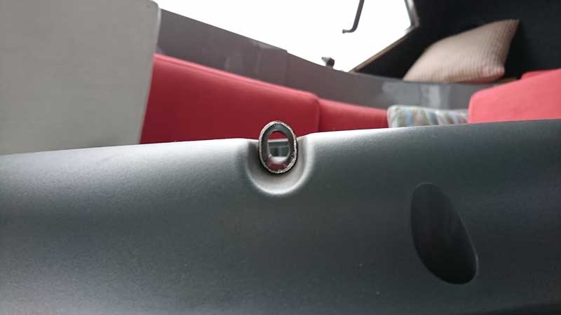
 )
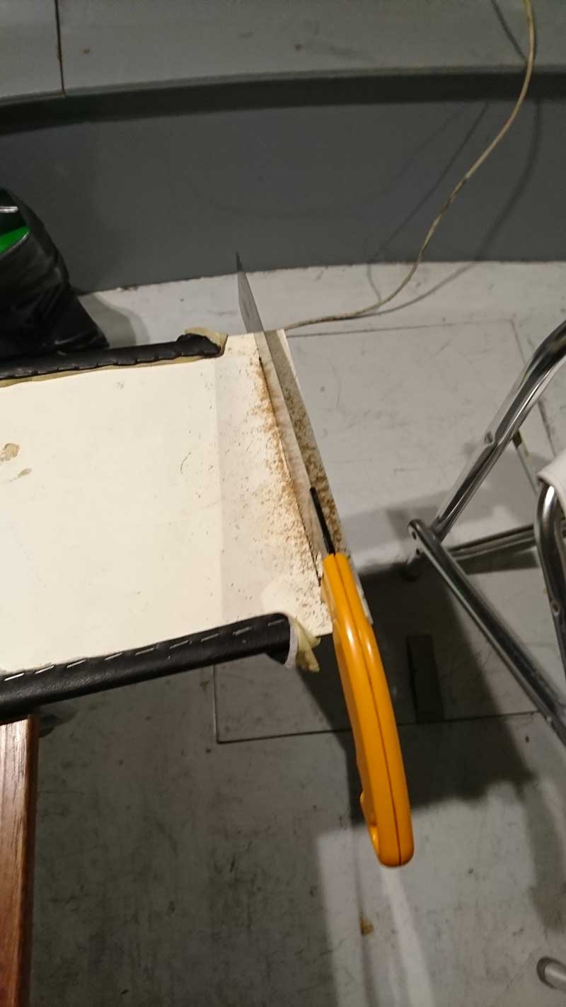
) So hammered the small sample to death made it into an oval shaped and sure enough it fitted just fine. Had to cut 7-8mm off the one side to make it flush, no big deal:
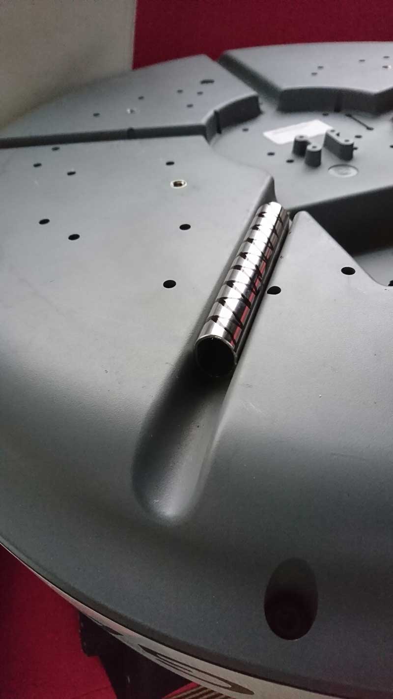
")
")