brccd
Member
Re: Pt2 - DIY Volvo Penta 2003 Instrument Panel
thanks for that link...I am interested in the solution with the arduino!
Bert
thanks for that link...I am interested in the solution with the arduino!
Bert
hello simonfe,
Hi, I know this is an old thread...I am having issues with my panel! Started looking at the schematic...and am thinking of re-doing it as well. Looks like you worked it all out however! Any chance on getting the info on your setup with the arduino?
Thanks,
Bert
Hi Bert
After my VP2002 suffered a permanent failure I have a few bits and pieces left over including a spare alarm lamp module which I'd be happy to sell.
Bought at a boat jumble a few years ago from someone who never got round to fitting a second control position on a motor boat, so it may never have been used, although it is missing one bulb which I used as a replacement when I needed one for my original panel . PM me if you're interested.
Bill
Hi,Re: Pt2 - DIY Volvo Penta 2003 Instrument Panel
Hi, I printed the the blue box with a 3D printer, I designed it on 3D CAD I will look to see if I can find the CAD data.
Have you considered fitting an exhaust temperature sensor?
My original plan was to fit this but have yet to do it, from what I have read the exhaust temperature rises MUCH more rapidly that the water temp so is a better/quicker way to detect overheat and prevent engine damage.
Simon
I've attached some files, shout if you need some explanation as the circuit is a pretty crappy sketch but you should be able to work out what I did!Hi,
I'd like to build the Arduino solution, one for my dad's 2002 with a dead alarm unit and one for myself. I have a MD2010D and we've had so many cooling issues (the most recent one was caused by tiny mussels living in the through hull in the saildrive), that I'd really like to add an exhaust temp sensor as well. Could you please share the Arduino code and how it's plumbed into the sensors?
Would be of massive help, thanks!
Rob
")
Thank you for your kind offer Magical Armchair
"Fortunately" I already have one that's fried, so I have enough to dissect for now. Cheers!
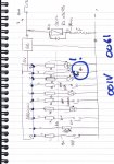
Hi Robert, I can't honestly say what the numbers are so probably ignore them... you need to put the relay coil in place of the lamp in the field coil as shown on the right. The relay contacts give you detection of alternator failure, eg fan belt failure.Hi Simon,
Thanks a lot for the info!
I couldn't quite work out how you're connecting to/from alternator 61? Did you mean that the N/C switch is the alternator? How is the supply to 61 for energising the stator?
What do you mean with "001V" and "0061", written in blue?
Robert
Pt2 - DIY Volvo Penta 2003 Instrument Panel
Following a whole tale of woe and frustration (see http://www.ybw.com/forums/showthread.php?406071-DIY-volvo-penta-instrument-panel), I decided not to spend the £200+ to get a replacement module, and with the help of circuit diagrams and some emails from the thread above, I set out to make my own, despite having not made any circuits since I was at school (a while ago).
All the components came from Maplins. No veroboard was in stock so I used plain board and pins.
I was unsure of the component wattages required so I hope I have erred on the side of caution.
The resistors are wire wound. I could not get a zenner diode of the right voltage (3.3v) at anything execpt low wattage, so I clustered 4 together in parallel.
I beefed up D1 as it is the main power into the circuit.
I took the original VP circuit diagram provided by CEPD, and added / modified it. My VP 2003 does not have glow plugs so there is one light redundant. I have added a circuit (the Aux circuit) to use that bulb for a switched (to negative) output from a cheap chinese ebay programmable temperature sensor which will get mounted on the exhaust.
My circuit diagram is below, along with the plan for the build, and a front and back photo of the finished board.
It tests out OK at home with a 12v bench supply.
It will get fitted to the boat tomorrow.
I am assuming I will not be able to recycle the 4 x bulb cluster as they are an integrl part of the broken module and it is all potted in, so I have instead gone with 4 x 4w BA9 bulbs and holders: I reckon the holders will fit somehow behind the coloured lens for the warning lamps. I will post some pics when this part is sorted.
So if you have a dodgy VP Control Panel, this is how to make your own and save several hundreds of pounds !! Enjoy.
View attachment 44960
View attachment 44959
View attachment 44957
View attachment 44958