faultfinding atillerpilot with multi meter

steve yates

Well-known member
Joined
16 Oct 2014
Messages
3,861
Location
Benfleet, Essex/Keswick, Cumbria
Visit site
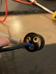
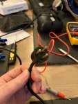
My tiller pilot, simrap tp-10, was playing up, intermittently at first, coming back with a wiggle of the wire, then giving up entirely. when I opened up the plug the blue cable was had pulled out from its connecting pin. While taking it apart I forgot which cable had gone to which pin (duh)
I have reconnected them both ways around, but on plugging into the socket aboard there is nothing from it whatsoever.
What tests should i run with my multimeter (total novice with one) to check whats what with the plug/cable on the tp and the socket on the boat?
Also, how do I know which pin to wire the pos and neg to? I have kind of assumed that with the fat pin up (unused) the blue goes to bottom left and the brown to bottom right pin, is there a way to use the multimeter to check the polarity of the matching socket holes to check this?
 

Attachments

  • simrad tp10-1.jpg
    simrad tp10-1.jpg
    108.9 KB · Views: 33
  • simrad tp10-2.jpg
    simrad tp10-2.jpg
    142.1 KB · Views: 32

eilerts

Member
Joined
26 Apr 2016
Messages
141
Location
Trondheim, Norway
Visit site
Installation guide for TP-10 says (for the cable attached to the unit)
Brown +12V
Blue 0V
So there you know the current configuration on the plug.
Turn on the power to the socket and check actual configuration of the socket with the multimeter. Select DC V on the multimeter, check that the black cable of the multimeter is pluggen in at COM. If you see a positive number on the meter, then you are pointing at the +12V with the red pin, if you see a negative number, then +12V is at the black pin. Change your plug accordingly.

I hope this is useful and I did not misunderstand your question. Check you own manual in case things are different there
 

steve yates

Well-known member
Joined
16 Oct 2014
Messages
3,861
Location
Benfleet, Essex/Keswick, Cumbria
Visit site
Pefect, that lets me check the polarity on the socket and i can wire the plug to match. It will also confirm I am getting 12v at the socket and there are no problems there.
Thank you.

To check continuity on the black cable from the tp itself, what kind of resistance readings should the meter show? Does anyone who has done this know?
 

andsarkit

Well-known member
Joined
27 Aug 2015
Messages
1,258
Location
Dartmouth
Visit site
Short the two probes together and this will give you a reading for the probe cables and meter error. Hopefully this will be small and not much more than 0.1Ω but some cheap meters may be more. Subtract this from the reading from the TP cable to give an accurate measurement. I doubt a basic meter will read to 2 decimal places but if the cable resistance is only about 0.1Ω you should be OK.
If you want to investigate further you can find the service manual online but it seems like you only have a power cable connection problem.
 

steve yates

Well-known member
Joined
16 Oct 2014
Messages
3,861
Location
Benfleet, Essex/Keswick, Cumbria
Visit site
Looks like I have a problem on the supply side as well as that loose cable. The sockets reading flickers between 0.24 and 0.04v , snd when i checked resistance across the tow sockets ( with power off) it just reads I. Next step is remove the socket and investigate but as it was pissing down I’ll leave that for a dry day.
 

andsarkit

Well-known member
Joined
27 Aug 2015
Messages
1,258
Location
Dartmouth
Visit site
If I understand correctly you measured the resistance between the + and - on the socket with the power switched off. This should be infinite or open circuit and may be shown as 0L (for overload) on the meter. That doesn't tell you much.
You definitely want to see a solid 12V on the power socket when switched on.
 

Alan S

Well-known member
Joined
5 Jun 2016
Messages
605
Visit site
There is a possibility that it has been destroyed by reversing pos and neg. A lot of 12V electronics is susceptible to this.
Ask me how I know ☹️
 

jamie N

Well-known member
Joined
20 Dec 2012
Messages
6,273
Location
Fortrose
Visit site
Steve, if it was me I'd follow the Volts. Go to the switch where you turn on the power to it. Check the Volts there, it's quite likely that the pins are quite close together so it could be an idea to put your negative probe directly onto the battery negative, having a lead with croc-clips is perfect for this. Then go to the + on the switch, and follow the Volts through any connectors or fuses to the socket. If you've Volts at the socket, then you're into the lead and the unit itself, which would be your next step.
With any fault finding (as you know fine) don't make the fault worse, thus separating the probes, which also gives one an extra hand free..
Apologies for writing in this manner as I do know you to be an intelligent and skilled bloke, but I wanted it to be as clear as if someone was explaining to myself!
 
Last edited:

eilerts

Member
Joined
26 Apr 2016
Messages
141
Location
Trondheim, Norway
Visit site
Looks like I have a problem on the supply side as well as that loose cable. The sockets reading flickers between 0.24 and 0.04v , snd when i checked resistance across the tow sockets ( with power off) it just reads I. Next step is remove the socket and investigate but as it was pissing down I’ll leave that for a dry day.
Not uncommon in a boat that there are two or more problems working together to confuse you. Before you get into destructive modus, and since you describe yourself as a total novice with the meter, are you sure you did not accidentally set the meter to AC V. If the selector does not say DC or AC, look for V and a double line, one whole and one dotted. (Same apology as above)
 

Alan S

Well-known member
Joined
5 Jun 2016
Messages
605
Visit site
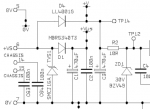
You should be OK with that. From the service manual:
View attachment 149131
View attachment 149132
Correct, but not in every case, at least not the VHF radio I bought in my local chandlery. Big spark then nothing! Realised right away what I'd done, took it back in all innocence and got it replaced free of charge.
Still pricks my conscience when I think about it.
 

andsarkit

Well-known member
Joined
27 Aug 2015
Messages
1,258
Location
Dartmouth
Visit site
Correct, but not in every case, at least not the VHF radio I bought in my local chandlery. Big spark then nothing! Realised right away what I'd done, took it back in all innocence and got it replaced free of charge.
Still pricks my conscience when I think about it.
Don't feel bad about it. Marine electronics should be designed for the the boating environment which includes untrained members of the public making incorrect connections. Skimping on the price of a protection diode which is pennies is not good practice.
 

Blueboatman

Well-known member
Joined
10 Jul 2005
Messages
13,733
Visit site
Old school suggestion
Wire a 12v incandescent type light bulb( so it draws a decent load , not some led thing ) to the autopilot plug and plug that in to the socket and see what you get
Hopefully a nice bright light
 

Blueboatman

Well-known member
Joined
10 Jul 2005
Messages
13,733
Visit site
That won't tell him if the polarity is right or wrong!
Correct
Adding : just touching the meter positive lead to one or other socket connector will show a +sign or not on the meter if it’s half decent, even the cheapos do that ..
( he could try it on a 1.5v battery at home first to see that too )
 

Boathook

Well-known member
Joined
5 Oct 2001
Messages
8,850
Location
Surrey & boat in Dorset.
Visit site
Pefect, that lets me check the polarity on the socket and i can wire the plug to match. It will also confirm I am getting 12v at the socket and there are no problems there.
Thank you.

To check continuity on the black cable from the tp itself, what kind of resistance readings should the meter show? Does anyone who has done this know?
Are you able to open up the socket ? They may have used the same colour wires which may assist.
 
Top