Expected Resistance of VHF Cable?

Ian_Rob

Well-known member
Joined
31 Jan 2008
Messages
1,123
Visit site
My VHF is playing up. My Hawk Aerial was replaced this time last year. The resistance at the coax plug is 9.9ohms. Is that within the range of a working antenna?

Thanks
 

andsarkit

Well-known member
Joined
27 Aug 2015
Messages
1,172
Location
Dartmouth
Visit site
I have no idea from the information you have given.
Assuming that is the DC resistance across the plug it seems a bit high but could be correct. The impedance of the cable is 50ohms but the DC resistance of 10m of cable is less than 1 ohm. There is often a matching coil across the coax at the antenna and so the resistance at the plug is then a few ohms.
If the cable is moulded into the antenna, the only way to check it is with a VSWR meter or a test to another radio preferably some distance away.
If you had measured the resistance when the antenna was installed and working you might notice if it had changed substantially.
 

jamie N

Well-known member
Joined
20 Dec 2012
Messages
6,089
Location
Fortrose
Visit site
End to end on the centre/core, should be virtually 0.00Ω. Core to screen should be infinity ∞, as in no continuity; above 20MΩ. Screen to screen should be 0.00Ω.
 

andsarkit

Well-known member
Joined
27 Aug 2015
Messages
1,172
Location
Dartmouth
Visit site
End to end on the centre/core, should be virtually 0.00Ω. Core to screen should be infinity ∞, as in no continuity; above 20MΩ. Screen to screen should be 0.00Ω.
Fine if you have a connector at the top of the mast and can get up there to disconnect it.
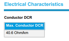
Typical values:
1711557849981.png
So about 0.8ohms for 20m of cable but most meters don't have much accuracy at low readings and you also need to subtract the resistance of the meter leads.
 

jamie N

Well-known member
Joined
20 Dec 2012
Messages
6,089
Location
Fortrose
Visit site
0.08Ω is virtually nothing. Calibrated VDM's are calibrated with the probes in place to ensure accuracy. I agree that the vast majority of meter's aren't going to be 'accurate' to scientific purposes, but they'll generally indicate a fault. On any coax with a fault, there'll be either an open circuit, or a short to screen, or high impedance end to end. It would appear that the OP is measuring 9.9Ω at the plug, I'd imagine that's reading across from centre to screen, which would indicate (to me) a short. Easily inspected at the VHF, but far more likely to have a fault at the exposed top of the mast.
 

ProDave

Well-known member
Joined
5 Sep 2010
Messages
15,148
Location
Alness / Black Isle Northern Scottish Highlands.
Visit site
If you can't unplug the aerial then any reading is meaningless unless you know how it is connected at the top. There will be some form of balun or matching transformer which may present anything from dead short at DC between inner and outer core or infinity.

The usual instrument to check the antenna is a VSWR meter.
 

Refueler

Well-known member
Joined
13 Sep 2008
Messages
17,672
Location
Far away from hooray henrys
Visit site
Lets be honest - playing with Meters and Ohms is a game you can play all day and not get anywhere ..

Usually if VHF is playing up (like to know how OP determines that) - is down to poor connection - often the centre lead is badly connected in the plug ..

Most VHF's nowadays have a Diagnostic menu option that checks antenna etc. But before using such menu option - remove any Splitter and connect antenna direct to VHF. If you run that option while splitter is connected - it will usually show FAILED.
 

john_morris_uk

Well-known member
Joined
3 Jul 2002
Messages
27,294
Location
At sea somewhere.
yachtserendipity.wordpress.com
0.08Ω is virtually nothing. Calibrated VDM's are calibrated with the probes in place to ensure accuracy. I agree that the vast majority of meter's aren't going to be 'accurate' to scientific purposes, but they'll generally indicate a fault. On any coax with a fault, there'll be either an open circuit, or a short to screen, or high impedance end to end. It would appear that the OP is measuring 9.9Ω at the plug, I'd imagine that's reading across from centre to screen, which would indicate (to me) a short. Easily inspected at the VHF, but far more likely to have a fault at the exposed top of the mast.
Many marine VHF antennas have the centre core of the coax tapped into a small coil of wire that matches the 5/8 wavelength of the vertical section to 50 ohms impedance. The top of the coil goes to the vertical whip and the bottom of the coil goes to the outer sheath of the coax. A resistance of a few ohms to DC at the bottom of the coax on these antennas is quite normal. 9.8 ohms seems a bit high but not beyond the realms of possible. A VSWR bridge will reveal what’s happening.
 

Martin_J

Well-known member
Joined
19 Apr 2006
Messages
4,257
Location
Portsmouth, UK
Visit site
Ian, as John Morris has just said.. many antennas have a base loading coil built into the base. It can, when the antenna is old, fill with water and affect the antenna.

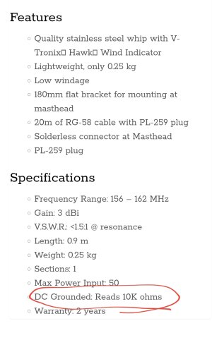
However, if you have for example the fairly common V-Tronix Hawk antenna at the masthead, then the DC resistance, when measured between centre and shield, with a simple multimeter will read just what you measured.

Screenshot_20240327-181805_Samsung Internet.jpg
 

Ian_Rob

Well-known member
Joined
31 Jan 2008
Messages
1,123
Visit site
Thanks for all the help. We are, wind permitting, relaunching tomorrow and another issue came up. I will check the readings again tomorrow.
 

srm

Well-known member
Joined
16 May 2004
Messages
2,773
Location
Azores, Terceira.
Visit site
My Icom AIS has a diagnostic that includes antenna. If you have a set with similar facilities swop the antenna leads to check the VHF antenna - assuming of course that you have sufficient slack in the antenna leads to allow them to be easily exchanged.
 

William_H

Well-known member
Joined
28 Jul 2003
Messages
13,660
Location
West Australia
Visit site
Any person who buys a new antenna would be well advised to measure DC resistance centre to screen before fitting and recorded for future reference. Too late for OP but data seems to indicate 10k dc resistance although less than 10 ohms would be common for some antenna and of course infinite resistance for a 1/4 wave whip.
Multimeters on low range typically 0 to 200 ohms. As said not very good at sub 5 ohms or so. You need a low range ohm meter. A rough lash up can be done by fitting a 12 ohm resistor across 12 v supply. This should drain 1 amp. Test on amp range on multimeter. Note actual current. Open that circuit and insert your circuit to be tested. Measure voltage across the tested circuit. A bit of maths the ratio of volt drop across the 12 ohm resistor compared to the volt drop across the circuit to be tested will give actual resistance. So a ratio of 12 v across resistor to 1 v across tested circuit gives 1 ohm tested circuit. V resistor divided by V circuit multiplied by resistor resistance gives result. Note this circuit will carry 1 amp in tested circuit (coax) which may cause a problem but then again may show up a bad connection. Use 120 ohm resistor for .1 amp current still quite accurate. Or use a LM317 regulator as a constant current source to simply measure volt drop at 1 amp or .1 amp. Of course any measurement of low resistance requires good connection of connection leads.
I used to use a low ohm meter in trade. It had a 1.5v dry cell and 1ma moving coil meter. The probes actually had 2 wires each probe current going down to probe head and then back to go down to other probe head and back via adjustment potentiometer and meter. Turn meter on and set meter reading to full scale. Then press probes on test item. Meter would read .006 ohms (max for a grounded radio rack of aircraft) at about 10% deflection. Can't recall actual circuit now but incredibly useful. (if you need it) ol'will
 
Top