big_s
New member
Hi all,
I am trying to create a new wiring system for an electric conversion for a small yacht that supports shore power charging and solar charging. The motor battery bank is 48V and the house 12V. Shore side AC is taken care of with a Victron Multiplus 48V unit (to be discussed later). I want to keep the system as simple and cheap as possible, so not using loads of Victron goodies!
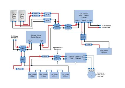
Here is a first draft of the system:

The blocks that show a circle inside a square are my representation of various switching types; double pole single throw, double pole double throw, voltage sensitive relay, input selector, contactor.
The solar power can be directed to either the motor side or the house side of the system using a DPDT switch.
If directed towards the house side, a VSR initially detects that the house battery is connected to the Victron charge controller before allowing solar power through. The house battery is fused close to the battery and has an isolator switch.
If directed towards the motor side of the system, the solar power feeds into the Renogy Rover boost charger which outputs 48V. A switch then selects between the 48V output of the boost charger or the 48V output of a Victron Multiplus (probably 800VA) and passes this to the motor battery bank. The motor battery bank can be isolated from charging inputs using a DPST isolator switch.
The motor system connects directly to the motor battery bank. It is fused and has an isolation contactor (key operated) to isolate the motor subsystem from the motor battery bank.
I would like to support charging of the house battery from shore power but not sure how that would integrate neatly and cheaply into this draft setup. Any suggestions appreciated.
Anyone out there got any initial comments? Trying to get as close to ISO compliance as possible eventually, so any tips in that direction also well received.
Many thanks,
S
I am trying to create a new wiring system for an electric conversion for a small yacht that supports shore power charging and solar charging. The motor battery bank is 48V and the house 12V. Shore side AC is taken care of with a Victron Multiplus 48V unit (to be discussed later). I want to keep the system as simple and cheap as possible, so not using loads of Victron goodies!
Here is a first draft of the system:

The blocks that show a circle inside a square are my representation of various switching types; double pole single throw, double pole double throw, voltage sensitive relay, input selector, contactor.
The solar power can be directed to either the motor side or the house side of the system using a DPDT switch.
If directed towards the house side, a VSR initially detects that the house battery is connected to the Victron charge controller before allowing solar power through. The house battery is fused close to the battery and has an isolator switch.
If directed towards the motor side of the system, the solar power feeds into the Renogy Rover boost charger which outputs 48V. A switch then selects between the 48V output of the boost charger or the 48V output of a Victron Multiplus (probably 800VA) and passes this to the motor battery bank. The motor battery bank can be isolated from charging inputs using a DPST isolator switch.
The motor system connects directly to the motor battery bank. It is fused and has an isolation contactor (key operated) to isolate the motor subsystem from the motor battery bank.
I would like to support charging of the house battery from shore power but not sure how that would integrate neatly and cheaply into this draft setup. Any suggestions appreciated.
Anyone out there got any initial comments? Trying to get as close to ISO compliance as possible eventually, so any tips in that direction also well received.
Many thanks,
S
Last edited:
