Diesel heater air intake

adhdan

Member
Joined
17 Sep 2023
Messages
102
Visit site
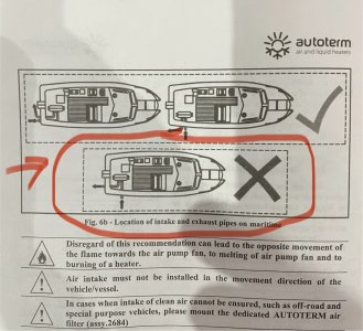
Replacing the diesel heater , the old one was rotten through & noisy. Got a 4kw planar/autoterm & the booklet says not to fit it with the inlet on the side & the exhaust at the back which is exactly how the previous heater was factory fitted…. I’m guessing it’s a fairly normal layout for boats? Whats the problem
 

Attachments

  • IMG_1923.jpeg
    IMG_1923.jpeg
    721.8 KB · Views: 43

jon and michie

Well-known member
Joined
28 Dec 2014
Messages
1,543
Visit site
If you fitted the Air inlet and the exhaust on the same side you will have a high chance of Death - ie the exhaust kicking out carbon monoxide while the air intake that the air gets warm will suck in the carbon monoxide and flood your cabin area with gas.

I ran the exhaust side out on the port side with the air intake heat side (not the combustion side) from the starboard side if this makes sense
 

PaulRainbow

Well-known member
Joined
16 May 2016
Messages
17,058
Location
Suffolk
Visit site
If you fitted the Air inlet and the exhaust on the same side you will have a high chance of Death - ie the exhaust kicking out carbon monoxide while the air intake that the air gets warm will suck in the carbon monoxide and flood your cabin area with gas.

I ran the exhaust side out on the port side with the air intake heat side (not the combustion side) from the starboard side if this makes sense
The diagram shows combustion intake and exhaust, so nothing to do with Co getting into the cabin.

The reasoning is, you don't want the combustion inlet sucking in hot exhaust gas.
 

adhdan

Member
Joined
17 Sep 2023
Messages
102
Visit site
If you fitted the Air inlet and the exhaust on the same side you will have a high chance of Death - ie the exhaust kicking out carbon monoxide while the air intake that the air gets warm will suck in the carbon monoxide and flood your cabin area with gas.

I ran the exhaust side out on the port side with the air intake heat side (not the combustion side) from the starboard side if this makes sense
i was asking about the burner air intake being on starboard & the burner exhaust out on transom so not together. The fitting instructions this is incorrect but says having the inlet/outlet (for the burner) next to each other is the correct way. The picture on my original post shows what i mean
 

adhdan

Member
Joined
17 Sep 2023
Messages
102
Visit site
The diagram shows combustion intake and exhaust, so nothing to do with Co getting into the cabin.

The reasoning is, you don't want the combustion inlet sucking in hot exhaust gas.
thats what i would of thought but the picture says that's incorrect and they should be fitted next to each other :unsure: . What i want to know is why is the diagram marked 'X' not allowed because that's how my previous heater is installed
 

PaulRainbow

Well-known member
Joined
16 May 2016
Messages
17,058
Location
Suffolk
Visit site
thats what i would of thought but the picture says thats incorrect and they should be fitted next to each other :unsure: . Can you see the image file on my original post? wondering if it posted properly
Yes, i see it OK.

I guess the problem is how the airflow around the transom works, allowing exhaust gases to be drawn forward with the possibility of being drawn into the inlet.

Why even have the combustion air intake from outside the boat ?
 

LittleSister

Well-known member
Joined
12 Nov 2007
Messages
18,650
Location
Me Norfolk/Suffolk border - Boat Deben & Southwold
Visit site
I believe the reason for having the combustion intake and exhaust on the same side (or both on stern) stern is so that the pressure at the two is equal (more or less), and you can't have a situation where the wind direction (or boat speed if high enough) results in excess or inadequate airflow through the burner because of a differential in air pressure.

p.s.
I would be interested to know what make of heater these instructions are for. I have in the past gone through the installation instructions for both my current ancient Ebersplutter, and for Autotermheaters (excellently detailed and clear instructions for the latter, by the way), and can't remember any such requirement.

pps
My old Ebersplutter combustion air intake is (effectively) in the cockpit, and the exhaust on the transom. I envisage reproducing that general arrangement when I install an Autoterm, and don't recall any suggestion that was recommended against.
 
Last edited:

adhdan

Member
Joined
17 Sep 2023
Messages
102
Visit site
Yes, i see it OK.

I guess the problem is how the airflow around the transom works, allowing exhaust gases to be drawn forward with the possibility of being drawn into the inlet.

Why even have the combustion air intake from outside the boat ?
Its how the original burner was fitted so the ducting is all there to connect the new one up ...nice and easy...except for the diagram saying dont fit it like this :rolleyes: .

I believe the reason for having the combustion intake and exhaust on the same side (or both on stern) stern is so that the pressure at the two is equal (more or less), and you can't have a situation where the wind direction (or boat speed if high enough) results in excess or inadequate airflow through the burner because of a differential in air pressure.

p.s.
I would be interested to know what make of heater these instructions are for. I have in the past gone through the installation instructions for both my current ancient Ebersplutter, and for Autotermheaters (excellently detailed and clear instructions for the latter, by the way), and can't remember any such requirement.

pps
My old Ebersplutter combustion air intake is (effectively) in the cockpit, and the exhaust on the transom. I envisage reproducing that general arrangement when I install an Autoterm, and don't recall any suggestion that was recommended against.
Its fitting instructions for autoterm AIR-4D. Now i think about it i reckon the starboard burner intake is behind an air vent grill so it isnt like a sealed bulkhead to outside but draws from behind the plastic grill where the engine compartment vents draw from which probably protects it from any issues with airflow.
 

jon and michie

Well-known member
Joined
28 Dec 2014
Messages
1,543
Visit site
The diagram shows combustion intake and exhaust, so nothing to do with Co getting into the cabin.

The reasoning is, you don't want the combustion inlet sucking in hot exhaust gas.
i was asking about the burner air intake being on starboard & the burner exhaust out on transom so not together. The fitting instructions this is incorrect but says having the inlet/outlet (for the burner) next to each other is the correct way. The picture on my original post shows what i mean
My Apologies
Jon
 

LittleSister

Well-known member
Joined
12 Nov 2007
Messages
18,650
Location
Me Norfolk/Suffolk border - Boat Deben & Southwold
Visit site
I now see that the notes under the OP's diagram say that -

'Disregard of this recommendation can lead to the opposite movement of the flame towards the air pump fan and to melting of air pump fan and to burning of a heater'

(Note to self - rtfm! :rolleyes:) So, as I suggested, this is about balancing intake and exhaust pressure.

I have now gone back to the full installation instructions and the text of that, at para 3.2 (page before the diagram OP reproduced), it says
'Air should be taken from well-ventilated areas or from outside of the vehicle or vessel'.
It seems to me that my cockpit intake for the burner air is consistent for that, but . . .

Now i think about it i reckon the starboard burner intake is behind an air vent grill so it isnt like a sealed bulkhead to outside but draws from behind the plastic grill where the engine compartment vents draw from which probably protects it from any issues with airflow.

It seems to me quite possible that that starboard burner intake, aft exhaust could lead to the very problem the caution note I quoted above highlights. Especially so given your engine will draw vastly more air from that intake area, and vastly more powerfully, likely leading to a negative pressure at the heater intake compared to the exhaust.

Why not just fit a new combustion air intake on the stern, or in some unenclosed space near it?
 

adhdan

Member
Joined
17 Sep 2023
Messages
102
Visit site
Why not just fit a new combustion air intake on the stern, or in some unenclosed space near it?
Its not that i cant fit a new air intake its that i would rather use the existing fittings/ducting if its safe to do so. I'll have a closer look at the vent setup when im next at the boat. If in doubt I'll just fit it internally. I should of read the whole thing instead of just the pictures 😁
 

BruceK

Well-known member
Joined
8 Feb 2015
Messages
8,327
Location
Conwy
Visit site
doh. Because when you come off the plain your diesel heater is going to fill with water. Same reason sailing flappy things dont like heater exhausts on the port or stbd sides is the most obvious. Yes the others are relevant but ........
 

Fire99

Well-known member
Joined
11 Oct 2001
Messages
3,603
Location
Bangor NI
Visit site
My heater has the combustion air intake on the inside of the engine room. Exhaust is on the port side high up the hull and the heated air (fresh air) intake is a huge intake hose linked to a moulding by the air intake for the engine on the same side.. The science behind it all I don't know..
 

PaulRainbow

Well-known member
Joined
16 May 2016
Messages
17,058
Location
Suffolk
Visit site
My heater has the combustion air intake on the inside of the engine room. Exhaust is on the port side high up the hull and the heated air (fresh air) intake is a huge intake hose linked to a moulding by the air intake for the engine on the same side.. The science behind it all I don't know..
Exactly how my current boat is, except i have 2 x 4kw heaters.
 

simonfraser

Well-known member
Joined
13 Mar 2004
Messages
7,489
Visit site
my heater has the in and out take on a double skinned metal tube, in / out through the same fitting !

i can smell it for a few secs when it starts up, after that nothing, CO monitor just above it, never gone off

1707894305040.png
 

PaulRainbow

Well-known member
Joined
16 May 2016
Messages
17,058
Location
Suffolk
Visit site
Ive got heater fitted & im re-lagging the exhaust. I've got it off & given it all a wrap in fibreglass exhaust cloth/tape along the entire length & secured it with metal ties then i was going to use rockwool pipe lagging. Saw it advertised in bigger sizes for chimney liners so im guessing its fine for the heat

Rockwool Rocklap 25mm x 1m Foil Faced Pipe Insulation - 60mm | Plumbing Superstore®
All i have ever used is this : EXHAUST LAGGING SLEEVE 22m to 24mm

As used on Planar, Eberspacher and Webasto heaters, never a problem.
 
Top