delivering power to a switch panel

steve yates

Well-Known Member
Joined
16 Oct 2014
Messages
4,106
Location
Benfleet, Essex/Keswick, Cumbria
Visit site
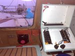
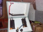
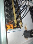
I have started bethfrans full rewire, but have hit a snag. The positive battery cables are 25mm sq, they go via a 121 switch, to a terminal post in the switch box. I had some 16mm battery cable, and some 6mm tinned, and had thought I would use one or the other to run the power from the post to the + brass busbars in the switch panels. However its a 6.3mm female spade connector that connects to the bars, and both cables seem too big to crimp onto it?
(I would be adding heatshrink over the cable and terminal after crimping) The 6mm cable is rated for 50a, the 2 panels can probably handle 30a each.


My questions are;
1) Can I safely use a thinner cable than 6mm to deliver that power or not? what size would be crimpable but carry enough current?
2)If not, can I get the power to the panel, preferably with another type of connector rather than adding other terminal blocks/busbars into the mix? Mainly,
2) Should havechecked this first, but I presume that single terminal post is enough and I can just crimp ring connectors onto 2 lengths of cable, 1 for each panel, and put them over the stud on top of the main battery cable?
and lastly,
3) I need to run a negative from the main busbar to the neg bus on the panel, same spade connector, for the illuminated switches. Am I right in thinking that my standard 1.5mm sq is fine for that? and would I just run 2 cables, 1 to each panel, form the rhs stud? or would I use individual screws just like any other load?

Thanks.
 

Attachments

  • bf-electrics-1.jpg
    bf-electrics-1.jpg
    81.1 KB · Views: 92
  • bf-electrics-2.jpg
    bf-electrics-2.jpg
    82.7 KB · Views: 95
  • bf-electrics-3.jpg
    bf-electrics-3.jpg
    92.2 KB · Views: 92
Yellow faston connectors will fit 6mm cable and are rated up to 20A. Not ideal for high current but should be OK if they are a tight fit.
1.5mm cable is fine for the switch illumination return .
 
Perfect thank you, I hadnt found anything like that on 12v planet when i looked, but searching your term brought it up. With everything running at full blast and even the deisel heater glowplug kicking in there should never be more than 15a being drawn through any one switch panel, so a 20a rating should do.
 
Thanks, yes I got a ratchet crimper from 12v planet and a hydraulic crimper from ebay. Gixer, yes I have oversized the wires generally and my runs are all short. Since I ripped all previous electrics out and am redoing them from scratch, I'm trying to do the job properly so I never have to touch any of it again.
 
Worth checking the max capacity of the switch panel. The ones that look like the ones u have seem to have a max capacity of 15A @ 12V. i would take a cable from your +post to each panel via a fuse to protect the panel, cable size subject to volt drop.
When i did mine i have split the loads into night and day, so a quick glance at the night panel in the daytime re-assures u that nothing has been inadvertently turned "on"
 
As mentioned above, you only need to size for the maximum load so could use smaller cable from the power post to the bus bar. If doing this, remember to have an inline fuse rated for the cable capacity otherwise you risk having an unprotected section of cable.

Another possibility would be to drill a hole in the bus bar strip and use a ring terminal. I think 16mm2 is still too large of a cable, but it would permit using a bigger cable diameter for greater current carrying capacity.
 
Worth checking the max capacity of the switch panel. The ones that look like the ones u have seem to have a max capacity of 15A @ 12V. i would take a cable from your +post to each panel via a fuse to protect the panel, cable size subject to volt drop.
When i did mine i have split the loads into night and day, so a quick glance at the night panel in the daytime re-assures u that nothing has been inadvertently turned "on"
The panels come with 6 5a fuses installed, so it should be rated for more than 15a I would have thought?
 
Would you not fuse as near to the battery as possible and then at each major change in cable size so you are adequately protecting the cable?

Just a thought based on what I am thinking/planning for when I do mine :unsure:

Cheers TC
 
It looks to me like some people have a first thought of 'what fuses do I need to survive this short circuit?'

It might be a good idea to consider reducing the possibility of short circuits in the first place.

That big stud with the fat red wire should have protection from black wires being pushed on to it when you shut the panel for instance.

The boat's made of plastic. Most short circuits will happen due to the wiring touching other bits of wiring, The place where most wiring is close to other wiring is right there in your switch panel.
Whatever fuses you install, the wiring 'upstream' of them needs physical insulation to prevent unwanted contact.
Good point and I have an insulated cover for the stud, and a cover to go over the busbar once all connections are made. The box is also quite deep, but of course a lot of wires are still going to end up in there.
 
It looks to me like some people have a first thought of 'what fuses do I need to survive this short circuit?'

It might be a good idea to consider reducing the possibility of short circuits in the first place.

That big stud with the fat red wire should have protection from black wires being pushed on to it when you shut the panel for instance.

The boat's made of plastic. Most short circuits will happen due to the wiring touching other bits of wiring, The place where most wiring is close to other wiring is right there in your switch panel.
Whatever fuses you install, the wiring 'upstream' of them needs physical insulation to prevent unwanted contact.

It's a fair comment, I would like to add that the people who are saying this are also supported by standards that advise this also. I'd always want to be on the right side of these.

On our boats, anything I have fitted has always exceeded two possible standards - the first one is to exceed the minimum required by legislation or insurance to avoid any issues, the second is the (equally as important) 'common sense' standard.

This basic guidance has served me very well in my professional career and on my own boats.
 
The panels come with 6 5a fuses installed, so it should be rated for more than 15a I would have thought?
it's unlikely that the overall panel rating is the sum of the outgoing fuse ratings. Worth checking the manufacturer/supplier's info. Then install a fuse at or just below that rating. Fuse outgoing circuits to suit their load/cable size.
 
it's unlikely that the overall panel rating is the sum of the outgoing fuse ratings. Worth checking the manufacturer/supplier's info. Then install a fuse at or just below that rating. Fuse outgoing circuits to suit their load/cable size.
No idea who the manufacturer is, i think i bought them on here a few years ago, from different folk. Neiither panel will ever have to draw more than 20a, so I’ll fuse the Power cables for that.
 
Top