Can Anyone help with a Circuit, Please?

VicS

Well-known member
Joined
13 Jul 2002
Messages
48,367
Visit site


.
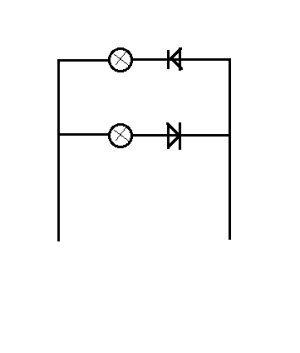
I think there is a way of doing the diode switching even is the light isn’t polarity sensitive. It appears possible with 4 diodes, maybe with just 2 on the negative connection to the fitting.

Your circuit will work when the lights ARE polarity sensitive but maybe not if they are not.

What I described in #12 will work for filament bulbs or led lights which are not polarity sensitive
1706993143236.png
 

Dellquay13

Well-known member
Joined
19 Feb 2021
Messages
895
Location
Boat at Milford Haven, Home in Chesterfield
Visit site
.


Your circuit will work when the lights ARE polarity sensitive but maybe not if they are not.

What I described in #12 will work for filament bulbs or led lights which are not polarity sensitive

View attachment 171743
Sorry, my typo there. I was trying to find a way for Polarity Sensitive LEDs on this particular common neg/ L1L2 positive wiring using just 2 core, since you have already described how to do it for non polarity sensitive LEDs.
 

Stemar

Well-known member
Joined
12 Sep 2001
Messages
23,122
Location
Home - Southampton, Boat - Gosport
Visit site
Thanks everyone, I've got it working at home using this.
I think there is a way of doing the diode switching even is the light is polarity sensitive. It appears possible with 4 diodes, maybe with just 2 on the negative connection to the fitting.

View attachment 171732
It also worked with 4 diodes but, obviously, 2 give a lower voltage drop, so no advantage to 4.

Now all I have to do is work out the best way to make reliable weatherproof connections for everything. Plan A is to to solder the diodes to the tiny wires coming out of the light and protect with heatshrink, then connect to the two-core with heatshrink crimp connectors.
 

Dellquay13

Well-known member
Joined
19 Feb 2021
Messages
895
Location
Boat at Milford Haven, Home in Chesterfield
Visit site
Thanks everyone, I've got it working at home using this.

It also worked with 4 diodes but, obviously, 2 give a lower voltage drop, so no advantage to 4.

Now all I have to do is work out the best way to make reliable weatherproof connections for everything. Plan A is to to solder the diodes to the tiny wires coming out of the light and protect with heatshrink, then connect to the two-core with heatshrink crimp connectors.
And a few wraps of self amalgamating tape?
 

VicS

Well-known member
Joined
13 Jul 2002
Messages
48,367
Visit site
Thanks everyone, I've got it working at home using this.

It also worked with 4 diodes but, obviously, 2 give a lower voltage drop, so no advantage to 4.

Now all I have to do is work out the best way to make reliable weatherproof connections for everything. Plan A is to to solder the diodes to the tiny wires coming out of the light and protect with heatshrink, then connect to the two-core with heatshrink crimp connectors.

Out of interest, what diodes are you using?
.
 

Stemar

Well-known member
Joined
12 Sep 2001
Messages
23,122
Location
Home - Southampton, Boat - Gosport
Visit site
1N4004G. It's what my local electronics component shop had. I would have preferred Shotkky diodes, but the only ones they had were signal diodes, with a tiny current capacity. They might (just) have done the job, but 'might just' isn't something I want at the top of my mast.
 

Dellquay13

Well-known member
Joined
19 Feb 2021
Messages
895
Location
Boat at Milford Haven, Home in Chesterfield
Visit site
1N4004G. It's what my local electronics component shop had. I would have preferred Shotkky diodes, but the only ones they had were signal diodes, with a tiny current capacity. They might (just) have done the job, but 'might just' isn't something I want at the top of my mast.
It’s possible the light is internally regulated to 5v or 9v etc and may dump the excess potential from a 12v supply anyway, so the slightly higher dropped voltage from a standard 1N4*** may be irrelevant
 

Stemar

Well-known member
Joined
12 Sep 2001
Messages
23,122
Location
Home - Southampton, Boat - Gosport
Visit site
After all this and getting the light working with diodes, I can't find a suitable switch to match the ones on the panel. :-(

A friend has suggested using the mast itself as the negative return. It's a GRP boat and the rig is electrically isolated from the batteries and engines. Can anyone see a problem with that?
 

Boathook

Well-known member
Joined
5 Oct 2001
Messages
8,079
Location
Surrey & boat in Dorset.
Visit site
After all this and getting the light working with diodes, I can't find a suitable switch to match the ones on the panel. :-(

A friend has suggested using the mast itself as the negative return. It's a GRP boat and the rig is electrically isolated from the batteries and engines. Can anyone see a problem with that?
I personally wouldn't. You will still have bits of wire linking sections up and every joint is another place for a fault to occurr.
 

PaulRainbow

Well-known member
Joined
16 May 2016
Messages
16,317
Location
Suffolk
Visit site
After all this and getting the light working with diodes, I can't find a suitable switch to match the ones on the panel. :-(

A friend has suggested using the mast itself as the negative return. It's a GRP boat and the rig is electrically isolated from the batteries and engines. Can anyone see a problem with that?
Not a good idea to use the mast for carrying any current.
 

Dellquay13

Well-known member
Joined
19 Feb 2021
Messages
895
Location
Boat at Milford Haven, Home in Chesterfield
Visit site
After all this and getting the light working with diodes, I can't find a suitable switch to match the ones on the panel. :-(

A friend has suggested using the mast itself as the negative return. It's a GRP boat and the rig is electrically isolated from the batteries and engines. Can anyone see a problem with that?
Can you keep the existing switch for on/off, and add an additional discrete switch for choosing tri or anchor?
 
Last edited:

rogerthebodger

Well-known member
Joined
3 Nov 2001
Messages
12,658
Visit site
After all this and getting the light working with diodes, I can't find a suitable switch to match the ones on the panel. :-(

A friend has suggested using the mast itself as the negative return. It's a GRP boat and the rig is electrically isolated from the batteries and engines. Can anyone see a problem with that?

I may have missed but what is the current switch like and how many positions and can you show the pic of the current connections
 

Boathook

Well-known member
Joined
5 Oct 2001
Messages
8,079
Location
Surrey & boat in Dorset.
Visit site
After all this and getting the light working with diodes, I can't find a suitable switch to match the ones on the panel. :-(

A friend has suggested using the mast itself as the negative return. It's a GRP boat and the rig is electrically isolated from the batteries and engines. Can anyone see a problem with that?
If the switches are the pull / push type I found some very similar on ebay a few years ago. Unfortunately my ebay order history doesn't go back far enough.
 

PaulRainbow

Well-known member
Joined
16 May 2016
Messages
16,317
Location
Suffolk
Visit site
After all this and getting the light working with diodes, I can't find a suitable switch to match the ones on the panel. :-(

A friend has suggested using the mast itself as the negative return. It's a GRP boat and the rig is electrically isolated from the batteries and engines. Can anyone see a problem with that?
What switches do you have Steve ?
 

Stemar

Well-known member
Joined
12 Sep 2001
Messages
23,122
Location
Home - Southampton, Boat - Gosport
Visit site
My current switches are like these.

onoff-round-mini-rocker-switch-with-amber-light-12v.png

I've only found one listing for a double pole on off on one, and they're out of stock.
 

rogerthebodger

Well-known member
Joined
3 Nov 2001
Messages
12,658
Visit site
I would use that switch to drive 2 relays one to switch the tricolour and the other to drive the anchor

!2Vdc would be connected to the center terminal of the switch and one relay would be connected to the one outer terminal and the other relay connected to the other outer terminal

The negative would be connected to the both relay negative

The + and negative connected to the 2 poles relay input the outputs would go to the twin wires to the lights reversing the polarity
 

Stemar

Well-known member
Joined
12 Sep 2001
Messages
23,122
Location
Home - Southampton, Boat - Gosport
Visit site
I did wonder about a relay, but wasn't anxious to add the extra current. Nosing around the internet, it does seem that relays are available that draw a few ma, so I'd still be better off than the original light with its bulb, They're designed to be mounted on a PCB, but I suppose I could solder the wires directly or, perhaps better, use a bit of stripboard, which I reckon would be more robust.
 

PaulRainbow

Well-known member
Joined
16 May 2016
Messages
16,317
Location
Suffolk
Visit site
I would use that switch to drive 2 relays one to switch the tricolour and the other to drive the anchor

!2Vdc would be connected to the center terminal of the switch and one relay would be connected to the one outer terminal and the other relay connected to the other outer terminal

The negative would be connected to the both relay negative

The + and negative connected to the 2 poles relay input the outputs would go to the twin wires to the lights reversing the polarity
This will not work because the switch is a simple on/off switch. The third terminal is for the LED negative.
 
Top