Can Anyone help with a Circuit, Please?

Stemar

Well-known member
Joined
12 Sep 2001
Messages
22,759
Location
Home - Southampton, Boat - Gosport
Visit site
I mentioned the difficulties I'm having replacing the existing twin cable in my mast, and a circuit using diodes was mentioned that would allow me to power the two lights individually from a twin cable. I understand the idea of having +12v on the red wire and ground on the black to operate one light and switching them around to power the other, but I can't get my head around the circuit to do it. Can anyone help, please?
 

VicS

Well-known member
Joined
13 Jul 2002
Messages
48,232
Visit site
I mentioned the difficulties I'm having replacing the existing twin cable in my mast, and a circuit using diodes was mentioned that would allow me to power the two lights individually from a twin cable. I understand the idea of having +12v on the red wire and ground on the black to operate one light and switching them around to power the other, but I can't get my head around the circuit to do it. Can anyone help, please?
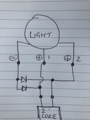
Simple.
Put a diode in seies with each . One way round with one. The other way round with the other.
You'll need diodes with a low forward volts drop though if brightness of the lights is important.
I can't spell it but Schotkey diodes are what you will need.

Edit: Schottky.
 

ylop

Well-known member
Joined
10 Oct 2016
Messages
1,608
Visit site
I'd recommend not using red/black for this - it will confuse your future debugging when not at +/-12V as you expect!

Will modern LED bulbs essentially do this (if installed correctly) without needing to add a diode just for the purpose?
 

PaulRainbow

Well-known member
Joined
16 May 2016
Messages
15,882
Location
Suffolk
Visit site
I'd recommend not using red/black for this - it will confuse your future debugging when not at +/-12V as you expect!

Will modern LED bulbs essentially do this (if installed correctly) without needing to add a diode just for the purpose?
If the LEDs are polarity sensitive (they are by default), than all you need to do is connect the two wires to opposite terminals, then fit a changeover switch at the helm. In one position one light works, the other won't because the polarity is wrong, flick the switch and the polarity reverses. This is how how NASA masthead LED's are wired by default.
 
Last edited:

VicS

Well-known member
Joined
13 Jul 2002
Messages
48,232
Visit site
If the LEDs are polarity sensitive (they are by default), than all you need to do is connect the two wires to opposite terminals, then fit a changeover switch at the helm. In one position one light works, the other won't because the polarity is wrong, flick the switch and the polarity reverses. This is how how NASA masthead LED's are wired by default.
This is true regarding discrete leds and the Nasa Supanova Combi, which is supplied with a pre-wired switch, but led replacements for navigation light bulbs supplied by Boatlamps, and presumably others, are not polarity sensitive.

.
 
Last edited:

VicS

Well-known member
Joined
13 Jul 2002
Messages
48,232
Visit site
Simple.
Put a diode in seies with each . One way round with one. The other way round with the other.
You'll need diodes with a low forward volts drop though if brightness of the lights is important.
I can't spell it but Schotkey diodes are what you will need.

Edit: Schottky.

ITYWF led replacements are not voltage critical therefore silicon diodes can be used without loss of brightness and visible range.
.
 
Last edited:

PaulRainbow

Well-known member
Joined
16 May 2016
Messages
15,882
Location
Suffolk
Visit site
This is true regarding discrete leds and the Nasa Supanova Combi, which is supplied with a pre-wired switch, but led replacements for navigation light bulbs supplied by Boatlamps, and presumably others, are not polarity sensitive.

.
Why not read what i typed, rather than just continually trying to pick fault ?

"If the LEDs are polarity sensitive"
 

VicS

Well-known member
Joined
13 Jul 2002
Messages
48,232
Visit site
Why not read what i typed, rather than just continually trying to pick fault ?

"If the LEDs are polarity sensitive"
YES!

I SAID, "THIS IS TRUE"


You even turn a statement agreeing with you into an argument. ............ hopeless!
.
 
Last edited:

VicS

Well-known member
Joined
13 Jul 2002
Messages
48,232
Visit site
Thanks everyone. I'll have a play, but it won't be until next week.

I have the Osculati light, and it's on the boat, so I don't know if it is polarity sensitive.
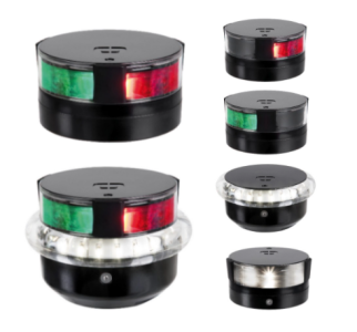
Which one. The tri-white ?

1706780629644.png
If so it appears to have three connections , A common negative and two positives , one for each light but this diagram does not tell which is what

1706781058532.png

Unless you can find some fitting instruction it's a case of checking it out to find out which connection is which or identifying them from the existing wiring.

Also checking to find out if the lights are polarity sensitive. If they are not, then connect one power supply lead to the common connection and the diodes , one one way the other the reverse way to the other two connections. Common the other ends of the two diodes and connect to the other power supply lead.

Sorry that is about as clear as mud in a wineglass but I don't have time to spare to do a diagram at the moment.

If the lights are polarity sensitive it will be difficult if not impossible to do what you want to do

Fitting instructions here https://www.osculati.com/document-h...o=FILE&docpath=DAMIS/Istruzioni_11.477.08.pdf

Pre-wired it seems
 
Last edited:

Stemar

Well-known member
Joined
12 Sep 2001
Messages
22,759
Location
Home - Southampton, Boat - Gosport
Visit site
Looking at it, it's actually a knock-off of the Osculati, but the wiring is the same.

Thanks, Vic, I think I've got my head round the masthead end, now I just need to work out the switch wiring, which I think I can work out.

I just need to find a 1-0-2 DP switch that matches the rest of my switch panel. All that'll be for next week as my weekend's pretty full.
 

VicS

Well-known member
Joined
13 Jul 2002
Messages
48,232
Visit site
Looking at it, it's actually a knock-off of the Osculati, but the wiring is the same.

Thanks, Vic, I think I've got my head round the masthead end, now I just need to work out the switch wiring, which I think I can work out.

I just need to find a 1-0-2 DP switch that matches the rest of my switch panel. All that'll be for next week as my weekend's pretty full.
Keep your fingers crossed for it not to be polarity sensitive.
If it is polarity sensitive it will be difficult, maybe not possible.

Why can't you run a 3 core cable to it?
3 x 1.0mm thin wall (ie 12 volt) cable ?
 

RupertW

Well-known member
Joined
20 Mar 2002
Messages
10,221
Location
Greenwich
Visit site
Looking at it, it's actually a knock-off of the Osculati, but the wiring is the same.

Thanks, Vic, I think I've got my head round the masthead end, now I just need to work out the switch wiring, which I think I can work out.

I just need to find a 1-0-2 DP switch that matches the rest of my switch panel. All that'll be for next week as my weekend's pretty full.
My switch panel didn’t allow for that as it switched only the positive wire and only that wire went out to the mast base. The negative (ground) in the boat is a set of common wires that run the length of the boat and branch off as needed for each device. So I had to put the DPDT switch after the branch in the cabin ceiling by the mast.

I feel there may have been a simple way of doing it at the switch panel without having to lead a special negative wire through all the impossible places but I haven’t thought of it yet and the current solution actually works pretty well and is discreet as it’s hidden by the mast base pillar.
 

Dellquay13

Well-known member
Joined
19 Feb 2021
Messages
833
Location
Boat at Milford Haven, Home in Chesterfield
Visit site
Keep your fingers crossed for it not to be polarity sensitive.
If it is polarity sensitive it will be difficult, maybe not possible.

Why can't you run a 3 core cable to it?
3 x 1.0mm thin wall (ie 12 volt) cable ?
Edit, I’ve just reread your original post about not being able to replace the existing 2 core cable so the question below is probably for someone else’s benefit more than yours… In your shoes I might be very tempted to resell the osculati copy and get the nasa one to go on your existing cable.

Risking my head above the parapet here, but as it is LED and so fairly low current consumption, do you need 1mm cable? The rating for 0.75mm or even 0.5mm 3 core may be enough, and helpful to fit in place of the old 2core rated for an incandescent lamp.
Just asking, please don’t shoot!
 
Last edited:

Stemar

Well-known member
Joined
12 Sep 2001
Messages
22,759
Location
Home - Southampton, Boat - Gosport
Visit site
Keep your fingers crossed for it not to be polarity sensitive.
If it is polarity sensitive it will be difficult, maybe not possible.

Why can't you run a 3 core cable to it?
3 x 1.0mm thin wall (ie 12 volt) cable ?
The existing 2-core cable is firmly stuck inside the mast. If I could get it out, I would.

I could try and get the head (probably not too difficult) and the foot (likely to be more problematic) off, but the diode trick is easier, if it works, so I'll try that first. I'm a bit of a coward when it comes to awkward jobs, something learned when owning old cars!
 

Dellquay13

Well-known member
Joined
19 Feb 2021
Messages
833
Location
Boat at Milford Haven, Home in Chesterfield
Visit site
Test your new light to see if it works with reversed polarity, if it does then simply fit diodes to the two positives, one forward one reverse.

If it is polarity sensitive, can you open the case and reverse the contacts for one of the circuits?

If you can’t open the case, is there another cable running up the mast with 12v? Can you safely share the negative with the other 12v cable and use your light 2core as L1 and L2 positives?
 

ShinyShoe

Well-known member
Joined
16 Nov 2013
Messages
1,782
Visit site
I'm sure you've thought of this, but you don't need to remove the existing 2 core that is stuck, just add a third core.

Which then leads me to ponder the possibility of something like a car body. The two cores supply the two different lights +ve terminal. The mast is connected to the -ve terminal on the light and the -ve terminal on the battery. Someone will be along to tell us why that is a bad plan...
 
  • Like
Reactions: RMC
Top