Will 3.3v serial work to send nmea to icom gx2100

GHA

Well-known member
Joined
26 Jun 2013
Messages
12,409
Location
Hopefully somewhere warm
Visit site
I'm rewiring a raspberry pi setup to use gpio pins as serial inputs through opto isolators, at the moment it's all serial/usb adaptors. But one of the USB adaptors receives wind data & also sends position data to the icom vhf 2100 at 4800 baud, so in the real world has anyone used 0/3.3v serial to send nmea to a gx2100 and is it high enough for the radio to use reliably?

Guessing good chance not, but easy if it does so worth asking if it works fine in the real world just in case before looking at alternatives.

TIA 😎
 

st599

Well-known member
Joined
9 Jan 2006
Messages
7,369
Visit site
Can't you use a MAX233 or similar board to convert 3.3 unbalance to the correct balanced level? Should cost about £2
 
  • Like
Reactions: vas

GHA

Well-known member
Joined
26 Jun 2013
Messages
12,409
Location
Hopefully somewhere warm
Visit site
Can't you use a MAX233 or similar board to convert 3.3 unbalance to the correct balanced level? Should cost about £2
Already have 4 way opto isolator board so should be able to just up the Vcc on the output of that, just uses another opto channel. Input to the radio isn't differential, single ended so just one wire & ground.
Found this, 5v should work 🤞

Version 1 talkers also had signal levels similar to that used in the computer ‘RS232’ standard. Here, the data signallingvoltage was up to +/- 15v, and the logical “1” or STOP bit state is defined to be within the range -15 to +0.5v. The logical“0” or START bit was defined to be within the range +4.0v to +15.0v.

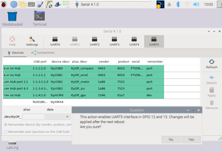
SignalK / Openplotter makes all so easy, click of a mouse to set up the output then route the gps nmea input to that serial output is a few moments, and you can use the serial input for another 0183 feed as long as the baud rate is the same. Such a powerful system for a cheap little raspberry pi 😎
1720515916024.png
 
Last edited:

GHA

Well-known member
Joined
26 Jun 2013
Messages
12,409
Location
Hopefully somewhere warm
Visit site
Already have 4 way opto isolator board so should be able to just up the Vcc on the output of that, just uses another opto channel. Input to the radio isn't differential, single ended so just one wire & ground.

Well that doesn't work 😁
If anyone else is thinking the same & the same opto board
https://www.amazon.es/-/pt/dp/B07HC5VV5X

On the input side between the cathode & ground there's a 3k resistor & LED, 3.3v doesn't create enough current going through those to open up the output, either shorting the LED or a 1k in parallel with the 3k does seem to work though. Also, between the input collector terminal on the output side there's a 3k so output is inverting, already bridged that & a 10K between the output & ground seems to be OK to create a non inverting output. This just with voltages, not tried nmea yet.
Sometimes cheap works, sometimes it needs a fiddle 🙂
 

GHA

Well-known member
Joined
26 Jun 2013
Messages
12,409
Location
Hopefully somewhere warm
Visit site
Can't you use a MAX233 or similar board to convert 3.3 unbalance to the correct balanced level? Should cost about £2
Oh hang on!!!!!!!
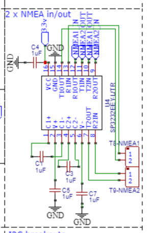
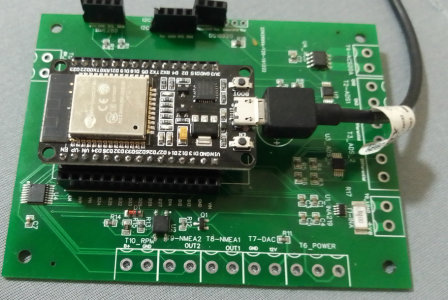
I've a board made by jlcpcb which an esp32 plugs in to & on there is an unused 2 channel max 3232, I can hopefully just cut the tracks to the esp pins & use that! Cost $0.21 from JLCPCB soldered onto the board 😎😎

Thanks for the reminder 💐

1720595582866.png
1720595644216.png
 
Top