Vosper Mini Fins Stabilisers retrofit on MiToS

  • Thread starter Thread starter vas
  • Start date Start date

vas

Well-Known Member
Joined
21 Jun 2011
Messages
8,217
Location
Volos-Athens
Visit site
Rebuilt is almost over, need a new project!

Silverdee offered the old stabs from his previous 16m trawler yacht on the for sale section, got them, received them last week, being studying the manuals, the various piece of kit I have in my garage and generally organising the work.
MiToS is on the hard getting ready for this operation.

I'll report on the various aspects of the work (dunno if it's going to be here or best in the main rebuilt thread) but got some observations/engineering Qs I want to place so thought best not to mix them up with the overall rebuilt.

The roadmap first:

decide on the placement, I think it's fixed to being as far to the front of the e/r and NOT as far back under the side cabins (too much in the front), ideal spot is where the diesel tanks (1200lt) live across and behind the cabins bulkhead and just in front of the two engines. Still along the 30% middle section of the WLL of the boat, so within the specs.

reinforce the hull, fairly easy as hull is 15mm ply on iroko frames (every 350-400mm) and along the length of the hull beams every say 600-700mm. So layers of plywood epoxied inside not only in the say 700X350mm patch the mechanism will be installed, but also on the surrounding patches. When finished, I'll add vertical (to the plane of the hull) beams around and across a few frames to distribute forces and stresses evenly.

fit the mechanisms, probably the easiest part of the job drill holes, lots of sika and bolt them down

organise the pump assembly/power/flow/etc. Need to discuss on that

fit the fins. Also need to discuss this!

get the "electronics" connected and working. Well being as low tech as it can get, plan is to use it as is for the first year and then develop some s/w h/w combo to control the double solenoids that push the oil to the two rams on each stab mechanism. Will take that easy, as I want a project to work with for sometime :rolleyes:

Some facts observations and questions:

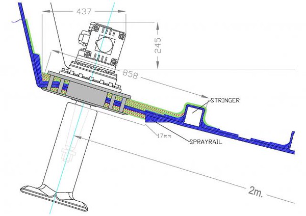
  • The Vosper Mini Fins came out of 35+ton semiD hull 16m long. They are going on a 11.5ton planning hull 13m long.
  • Fins are 0.42msq and fairly squarish (not oblong as the newer seem to all be) 0.85m [EDIT: 0.95m at the hull side, 0.85 is an approx average length] long by 0.53m high (compared to my estimated 1.25X0.5 approx 0.6sqm for BlueAngel at almost double the length and don't remember how many times the weight of MiToS).
  • Fins are amazingly heavy (not talking about all the bronze alloy units bolted on the hull with the twin rams and solenoids on top, they seem reasonably robust and heavy, talking about actual fins alone!)
  • System was not capable of stabilisation at rest.
  • According to SilverDee, system was not man enough for the 35+ton trawler even at speed.

From all the reading and following as best as I can the discussions on the Match built threads and Blue Angel retrofit of electric stabs it seems to me that:
  • units are large enough for MiToS - maybe a bit too large, but I can live with that and hopefully manage to get them to be useful at stabilising at rest as well.
  • Don't like the fin shape, size and especially weight (must be at least 50kg each maybe more)

Qs:
Anyone would know what material the fins are made of in these old stabs? I'll try drilling a small hole in various places and check myself
Any reason not to chop them down to say 0.85mX0.40-0.45m for now?
If I have time (would like MiToS back in the water by the end of May) I'd chop them more drastically down to 0.85X0.20 and built a angled part another 15-20cm making sure that at rest this new part is parallel to the sea. The new built up would be foam and mat and epoxy. I'd also like to soften the front side of them as its too vertical and there's material to remove there slopping it further. Sorry sketches will follow tomorrow, too tired now!
This way I can reduce the weight of them considerably as well.

On the pump oil supply front, I currently have two smallish pumps (approx 150mm cube, local experts estimate 6.5lpm@1500+psi@1400something rpm) one feeding each stab. Documentation mention 1.75gall/min@1200rpm (er, what gallons are these??? anyone would know as 6.6 vs 8lpm is a substantial difference!)
Each pump should "steal" 2.5-3HP(max!) from the engine.
Roll period in secs relates to suggested pump rpm, I'd opt for the fastest rpm i.e. closest to the 1500rpm limit.
Further the manual warns against fitting the 4.5sqft (0.42sqm) fins to vessels capable of speeds over 16kn, which I find interesting but odd.

Plan here is to leave them aside and instead of spending 700euro for two electrowhatever clutches for their pulleys, spend that money on getting a larger single pump mated to a 3phase el. motor say 5.5hp (or even 7.5hp) Just under 400euro for the 5.5hp combo or 500euro for the 7.5hp setup.
Then run this from an inverter from the 8KW Mase generator onboard, without messing with engines as well as being able to test/check and run the system on the hard using shore power (pushing it a bit, but I can just do it by wiring the motor straight to shore without interfering with boat electrics)
If it works the extra bonus is that I can get some sort of help at rest as well (and that's the other large debate)
Q:
  • does the above sound reasonable, sizes/hps make sense?
  • Where can I find a 1phase in to 3phase out 5.5KW inverter? Or do I scrap the 7.5hp motor and go for 5.5hp and a 4KW inverter (which exists!)


I understand it's slightly unstructured and asking some qs that are akin to how long is a piece of string, but any suggestions would help me reduce mistakes and keep costs down at least for the first install and testing.

cheers

V.
 
Last edited:
some measuring, mocks, sketching on the hull and a couple more Qs, hope it's picked up by the ones in the know!

first, the plan to have the stabs placed at the e/r is a no go.
Following careful measuring, e/r placement is way too aft:
Stab axle would be 6.55m from bow and 3.70m from stern :(
Forward tip of the fin would be 6.45m from bow and aft tip of the fin ending at only 2.75 from stern.
Cannot go further towards the bow as there's not enough clearance under the tanks:

stabs_er_mock.jpg


Bear in mind that I'm simply laying the mock on the hull ply, but this is going to be reinforced with most likely 3 layers of 20mm marine ply to an overall thickness of 75mm, plus the cross frames on both directions. So going to be a fairly thick area there.

So moved down to the cabins, lifted port cabin mattress and ply, and surely enough there's plenty of easily accessible space for them there:

stabs_portcabin_mock1.jpg


stabs_portcabin_mock2.jpg


stabs_portcabin_mock3.jpg


stabs_portcabin_mock4.jpg


stabs_portcabin_mock5.jpg


Stab axle will be 5.40m from bow and 4.80m from stern (this aft measurement is a bit vague as the stern bulges approx 30cm in the middle, measurements I'm giving are for side of hull)
Forward tip of the fin would be 5.30m from bow and aft tip ending 4.00m from stern which I think is more appropriate. Actually fins will be moving under the tanks so v.close to the COG of the boat.
I hope this is acceptable placement along the length of the craft. That's how it looks on the side elevation I'm playing with and checking all new construction on...

side_elevation2_HT17.jpg


Outside now, some pics with the light blue door frame (don't ask where it comes from and why it was laying there!) exactly where the axle would be:

stabs_outside_layout1.jpg


stabs_outside_layout2.jpg


stabs_outside_layout3.jpg


Second issue is how far OUT they can be placed. To be honest I can get them as close as 200mm from the end of the hull.
Hull deadrise there is 20degrees.
shortening the stabs a bit (as in reducing their "height" from 530mm down to say 450mm) at rest the stab is definitely within the footprint of the hull, easily.
This way I'll go down from 0.42sqm to 0.355sqm with better proportions 0.95X0.45m.

HOWEVER, if they move, the outward movement will get the tip of the fin almost 150mm outside the waterline footprint of the hull. Is that acceptable?
Actually the top edge of the fin will be flirting with fresh air :rolleyes: on the outward ending of the movement. Is that something that happens?
Looking at the section posted by Bart on his thread for sure the fin goes outside the hull footprint on the outward movement but it doesn't look like coming out of the water (if the wiggly line denotes waterline, it's almost 300mm upwards of the chine!):
i-vcbJJJz-L.jpg

JFMs M videos show water turbulence, but you cannot actually see the fin surfacing.
My hull chine (or whatever you call the change from the side to the 20 degrees going towards the keel) is only 80-100mm below waterline where the fins will be fitted whereas looks like that on the 70-80ft hulls, there's 300+mm there!
Is that "allowed" or should I move the fins further in?
Actually the fin axle is at 1.65m from the keel, full width to the chine is 1.95m, so 0.30m from the chine. I can go 0.20m or 0.40m, the former will be edgy, the latter will reduce leverage (I guess) a lot, reducing the effectiveness of them.
FWIW, fin rotation seems to be 30degrees either way from center, following pics show fin movement for 45, 40deg as well as 30. For some odd reason I had assumed it's 40deg, but just now checked with daughter's protractor.

stabs_outside_layout4.jpg


I'll start preparing the ply sheets (well, after buying a sheet tomorrow!) and getting the reinforcements there (a 4kg pot of epoxy should be enough I recon), will be the end of the week before I start thinking about drilling and securing the units in place in port side. Stbrd is a bit dodgy as I either have to move the aircon out of the way, or lift it up 300mm, or drill a LARGE inspection hatch under daughter's bed bulkhead and do all the installation through the hole...

hope for some feedback!

cheers

V.
 
OK ... here's some thoughts and I think you may have planned location about right ...

..... based upon Navigator ... heavier engines (3 T + gearboxes ) and 1,700 L fuel behind engines (50% fuel onboard when lifted) and a 3.5 KW Onan generator far aft.

Twin straps rear when lifted and single front.
The aft of the two rear straps approx 30 Cm in front of where shaft comes out (underneath Tanks) and the front of the rear straps right at exhaust outlet front curve (approx at Aft Engine mounts)...

The rear straps combined carried 13 T
The single front strap carried 5 T

Total lifted weight of 18T ... so a bit heavier than you and a couple of Ft longer ... I'll try to dig out lifting pictures...

ooh ... and I think I would have liked to strengthen the adjacent sections as well ... perhaps not as heavy, but twisting/stress is bound to transfer beyond installation location...
 
Last edited:
first, the plan to have the stabs placed at the e/r is a no go.
Following careful measuring, e/r placement is way too aft:
Stab axle would be 6.55m from bow and 3.70m from stern :(
Forward tip of the fin would be 6.45m from bow and aft tip of the fin ending at only 2.75 from stern.
V, you're talking of measurements taken along the waterline, I suppose?
Anyway, an axle position 64 and 36 percent respectively from the bow and the stern doesn't seem necessarily wrong to me, for a P boat.
Besides, there's something that doesn't stack up in your fin measures, because they would imply that:
- the fins are 1,05m long (not saying they can't be, but if so they are unnecessarily big for the boat, imho).
- the forward side extends only 10cm in front of the axis, and the aft side 95cm. I'd expect that kind of shape in zero speed fins, but they aren't, or are they?
Just in case, be aware that it's pointless to fit zero speed fins on non-zero speed actuators (even if feasible in most equipment), because they are NOT more efficient under way, and it's better to have the normal, more "balanced" (if that's the right wording) fins, to reduce the load on the actuators AOTBE.
 
Hi Vas. I've owed you comments for ages on this topic, sorry. A few thoughts:

1. Fore aft placement looks good to me.
2. Following up mapism's comment, your sketches with fin shaft at front of fins look like zeros, but these are not zeros. Unless I'm remembering badly, the fin shafts are near central on the fins to create the "balance" that mapism refers to. Thus the actuators are tiny, and nothing like your cardboard templates. I think they are single cylinder.
3.. hence there is no possibility to use them as zeros unless you fit bigger cylinders and chop off the fin fronts (and write software of course). But no worries there- underway stabilisation is a great thing.
4. I'm a little worried whether they will work at all @ 20+ kts due to the small cylinders but no harm trying.
5. In due course, if you are able to build a solid state control board to replace the processing gyro controller that would be awesome potentially, but try the old kit first because of course a precessing gyro is theoretically a perfect controller so you might just be able to improve what you have.
6. As James will have told you, both fins are new. The last two minis that vosper ever had in stock. There are no more!

Looking forward to hearing how this goes. Super project and you're the guy to do it. Underway stabilisation in 40 footer is an awesome upgrade and the effect in a big beam sea will bring a big smile to your face. Much better than any seakeeper underway.

As an aside, did folks see that the seakeeper founders sold out last week? To a mini Melrose style firm called Madison Industries in Chicago. Good going.
 
Last edited:
On pumps, I gotta say I struggle with your electric idea. They won't stabilise at rest for reasons stated and so you should just get an engine driven pump. Run off pto, or at this size a vee belt. Imho.
Did the silver dee kit not include any pump? They were driven off vee belts, mounted at front of engine, iirc.
 
Did the silver dee kit not include any pump? They were driven off vee belts, mounted at front of engine, iirc.
Fwiw, that's exactly the setup which worked just perfectly in my old lady's Naiad stabs (with two belts in parallel).
For 2 decades and counting, without ever changing the belts - go figure!
In fact, I fully agree that going electric in a non-STAR installation is totally pointless.

PS: even more so when the fin actuators are hydr anyway!
 
Last edited:
As an aside, did folks see that the seakeeper founders sold out last week? To a mini Melrose style firm called Madison Industries in Chicago. Good going.
I didn't read about that.
Are you suggesting that's good going for the founders, or for the NewCo...? :)
 
sorry, longish post as I'm trying to answer all in one :D

OK ... here's some thoughts and I think you may have planned location about right ...

..... based upon Navigator ... heavier engines (3 T + gearboxes ) and 1,700 L fuel behind engines (50% fuel onboard when lifted) and a 3.5 KW Onan generator far aft.

Twin straps rear when lifted and single front.
The aft of the two rear straps approx 30 Cm in front of where shaft comes out (underneath Tanks) and the front of the rear straps right at exhaust outlet front curve (approx at Aft Engine mounts)...

The rear straps combined carried 13 T
The single front strap carried 5 T

Total lifted weight of 18T ... so a bit heavier than you and a couple of Ft longer ... I'll try to dig out lifting pictures...

ooh ... and I think I would have liked to strengthen the adjacent sections as well ... perhaps not as heavy, but twisting/stress is bound to transfer beyond installation location...

Alf,

getting confused as some Mysteres (the JC variety like MystereMarcus) are on V-drives, yours IIRC is on proper shafts but seems that tanks are aft between engine room and lazarette? So completely different layout and slightly different balance.
Yep, strengthening will not only be on the area where the fins will fit, will be on one or two frames forward and aft as well (actually one forward and two aft)
Bulkheads do help and there's one aft of the fins (if they are finally placed on the cabin area and not e/r as MM suggests is acceptable)
Anyway, we shall see where the fins should fit.

V, you're talking of measurements taken along the waterline, I suppose?
Anyway, an axle position 64 and 36 percent respectively from the bow and the stern doesn't seem necessarily wrong to me, for a P boat.
Besides, there's something that doesn't stack up in your fin measures, because they would imply that:
- the fins are 1,05m long (not saying they can't be, but if so they are unnecessarily big for the boat, imho).
- the forward side extends only 10cm in front of the axis, and the aft side 95cm. I'd expect that kind of shape in zero speed fins, but they aren't, or are they?
Just in case, be aware that it's pointless to fit zero speed fins on non-zero speed actuators (even if feasible in most equipment), because they are NOT more efficient under way, and it's better to have the normal, more "balanced" (if that's the right wording) fins, to reduce the load on the actuators AOTBE.

Sorry P.,

probably made a 10cm mistake on my calcs. Fins are 95cm on the hull side, 80 at the other end [ EDIT 60cm, sorry messed that up!], 53cm "high". Axle is indeed 100-120mm [EDIT: doh 240mm top, 100mm bottom] from the front so it's zero speed territory as far as fin layout is concerned.
Fins actually look very similar to the Naiad ones as listed in this pic, complete with twin rams:
fins-31-300x237.jpg

Original manual has a nice sketch, sorry left it larger as it's difficult to figure out what's what on a 800px image:
vosper_stab.jpg


I'd rather have the fins at the e/r but the analogy seems a bit wrong to me, mind 85%+ of the time I'm on D speeds wont go fast unless it's completely flat, crew is not so keen of being bumped around and wife is not happy hearing, or now that i'm fitting fuel flow thingies (more on that in another thread soon!) seeing, intrastellar (for MiToS!) fuel consumption figures...

I still feel e/r option is too far back and worried for fishtailing!


Hi Vas. I've owed you comments for ages on this topic, sorry. A few thoughts:

1. Fore aft placement looks good to me.
2. Following up mapism's comment, your sketches with fin shaft at front of fins look like zeros, but these are not zeros. Unless I'm remembering badly, the fin shafts are near central on the fins to create the "balance" that mapism refers to. Thus the actuators are tiny, and nothing like your cardboard templates. I think they are single cylinder.
3.. hence there is no possibility to use them as zeros unless you fit bigger cylinders and chop off the fin fronts (and write software of course). But no worries there- underway stabilisation is a great thing.
4. I'm a little worried whether they will work at all @ 20+ kts due to the small cylinders but no harm trying.
5. In due course, if you are able to build a solid state control board to replace the processing gyro controller that would be awesome potentially, but try the old kit first because of course a precessing gyro is theoretically a perfect controller so you might just be able to improve what you have.
6. As James will have told you, both fins are new. The last two minis that vosper ever had in stock. There are no more!

Looking forward to hearing how this goes. Super project and you're the guy to do it. Underway stabilisation in 40 footer is an awesome upgrade and the effect in a big beam sea will bring a big smile to your face. Much better than any seakeeper underway.

As an aside, did folks see that the seakeeper founders sold out last week? To a mini Melrose style firm called Madison Industries in Chicago. Good going.

no problem John, my comments following your numbering:

1. you mean on this last pic I posted? I also much prefer them like that!
2. you're probably mixing them with Jame's Aquastar fins, the ones I've got are identical to the pics I've linked and posted above.
3. actually considering that these fins and twin rams were almost good for a 37ton 16M trawler, I'd expect they'll be able to shift enough water for zeroish stabilisation on an 11ton 13M planning hull as MiToS' Will have to reduce them in size and alter the shape, so plan is to cut a slice off the bottom for starters and see for next year...
4. no worries, as stated above haven't bothered with more than 17-18knots and that for short period of time with extremely flat seas.
5. yep, thought I mentioned it, of course I'll start with the original h/w box that James sent me with the two knobs, center/stabilise and Min/Mid/Max. Next winter, I'll start organising code for a solid state equivalent (which will probably be a cigarette packet size and not a 4kilo 30X20X20cm box!)
6. oh, didn't mention anything, I realise they are the 4.5sqf ones (ie. the large size) didn't know they were new. BTW, do you happen to know what they are made off? If you'd say they are lead, I'd believe you! 50kilos each!!! Drilling some test holes tomorrow to see what'll come out :rolleyes:

I'll let you all posted for sure! should be interesting to see how that goes.

On pumps, I gotta say I struggle with your electric idea. They won't stabilise at rest for reasons stated and so you should just get an engine driven pump. Run off pto, or at this size a vee belt. Imho.
Did the silver dee kit not include any pump? They were driven off vee belts, mounted at front of engine, iirc.

James kit included two pumps. Considering that I may be able to use it at rest, and considering that my typical travelling is either 1200rpm or 2200rpm I do need to sort out a coupling thing that costs 700euro (I was told at least) for the two pumps to run them off v-belts. Annoyingly I'd need a system that runs at full speed at lower engine revs which means will be at pump breaking territory when planning, wonder how James dealt with that.
Hence thought that I'm better off buying a 3phase 4KW motor and a 5.something hp pump and running them off the generator. Easy to bleed and setup, easy to check my hardware (and s/w) on the hard without running the generator or engines.
Sure if it turns out it's no good for rest operation, I can remove that and hook up the pumps on an engine.

However, as I've said, fins look STAR, these are twin rams on each, was specced for a much larger and heavier craft, it may just work :D

cheers

V.
 
Last edited:
Ah good stuff vas. I wasn't remembering well. I think the fins are cast phosphor bronze btw! You could trim off the leading edge to make them even more STAR like.

Yes it was the aqua star 74 that had the horrible puny single cyl jobs. The vospers were over specced. You could STAR-ize them.

The engine driven pumps are fine if you run them over a wide rpm range. I don't understand why you need special coupling. They are positive displacement variable displacement pumps with a swash plate that automatically regulates the displacement via a feedback hose. Normal stuff. Btw Searanger on here is a pump expert/supplier and supplies James with much of his hydraulic stuff including ptos.
 
I vaguely think I have a spare 230v single phase to 3ph inverter/converter. In a box somewhere. It was changed under warranty but I think it's ok. Was for my airco on current Sq78- it ran a 6 tonne domestic chiller. I need to check I have it and find the spec. If it's useful I can mail it to you- pity I missed the 2 pallet shipment that James just sent to you. (Was that fun at import/customs btw?). He and I should be better coordinated ( even though we just spent weekend together and jimmy builder too!). Will be next weekend earliest that I could check this inverter thing.
 
I'm pretty sure the vosper kit hydr vales are open/shut, not proportional. These days STAR invariably use proportionals. But in a "don't run before walk" approach, if you could make a black box to run these fins as STAR using non prop valves that would be a great project. Then you could upgrade to proportionals (catalogue rexroth stuff) and refine your software. You will definitely get a big cigar for all this Vas. :encouragement:

Remember STAR stabilising a MiToS sized boat is hard. The roll period is short. The fin has to react fast when the roll starts or it's too late. Your STAR control gear will have to deal with this. Great project. Very challenging.
 
Last edited:
1. you mean on this last pic I posted? I also much prefer them like that!
Yes exactly. The aqua star fish tailed with aquastar's factory install but is now perfect with them moved.

Here is aquastar factory vs current fins...
silver%20E%20stabs%20posn.jpg


And here is my boat fin pos...
GAoct2012profileandfly.jpg
 
multiple replies and some more info and drawings:

Ah good stuff vas. I wasn't remembering well. I think the fins are cast phosphor bronze btw! You could trim off the leading edge to make them even more STAR like.

yep, more like it.
Scared with cast phosphor bronze fins, started drilling them about :D, they are nicely cast polywhatever (as in some sort of solid plastic cast on probably phosphor bronze insert for the ss shaft and key to mate)
So modding them is going to be easy!

Few pics of them and dims:

no, that's not a plastic eating worm, just my 3mm drill going through every 60odd mm to make sure it's the same all around:
stabfin_1.jpg


stabfin_2.jpg


side view, looking at them, they indeed look new, just had a coat of primer and redish antifoul that conveniently flaked out :D :
stabfin_3.jpg


hope 14cm thick is okayish (wouldn't mind it thinner but no idea what sort of stresses these things go through)

stabfin_4.jpg


stabfin_5.jpg


stabfin_6.jpg


and that's the 400mm dia plate that goes under:

stabfin_7.jpg


Plan is to form them as in the white shape in the following autocad drawing:

stabfin_design1.jpg


Note the changes:

Forward slope from 80degrees down to 70 so smoother on entry
reduce height from 530 to 400mm
finally ADD material to change the aft edge from 117deg to just 95.

Area wise:
original 0.41sqm
proposed 0.35sqm

however I think I'll just go for the first step to 0.31sqm (ie. just cutting and not building the fin ending)
Length on the hull side remains 0.95m. Shape becomes more reasonable and smaller as per MiToS size.

The engine driven pumps are fine if you run them over a wide rpm range. I don't understand why you need special coupling. They are positive displacement variable displacement pumps with a swash plate that automatically regulates the displacement via a feedback hose. Normal stuff. Btw Searanger on here is a pump expert/supplier and supplies James with much of his hydraulic stuff including ptos.

John, thanks for the link, I'll PM Searanger as hydraulics are not (yet!) my thing and reading the Vosper manual it does mention not to run the pumps higher than X rpm (1900iirc, maybe less)


I vaguely think I have a spare 230v single phase to 3ph inverter/converter. In a box somewhere. It was changed under warranty but I think it's ok. Was for my airco on current Sq78- it ran a 6 tonne domestic chiller. I need to check I have it and find the spec. If it's useful I can mail it to you- pity I missed the 2 pallet shipment that James just sent to you. (Was that fun at import/customs btw?). He and I should be better coordinated ( even though we just spent weekend together and jimmy builder too!). Will be next weekend earliest that I could check this inverter thing.

Luckily no import/customs as it's coming from a (still) EU country (dunno for how long more though, but that's for the lounge not here...)
Nobody bothered, checked or figured out what all that was, they just saw a massive chain and a big Bruce anchor on top, so was "the pallet with the chain" :D

Considering the pump and 3p motor is 400euro all in, if you do have a spare inverter man enough for 4-5KW I'd be obliged!

I'm pretty sure the vosper kit hydr vales are open/shut, not proportional. These days STAR invariably use proportionals. But in a "don't run before walk" approach, if you could make a black box to run these fins as STAR using non prop valves that would be a great project. Then you could upgrade to proportionals (catalogue rexroth stuff) and refine your software. You will definitely get a big cigar for all this Vas. :encouragement:

Remember STAR stabilising a MiToS sized boat is hard. The roll period is short. The fin has to react fast when the roll starts or it's too late. Your STAR control gear will have to deal with this. Great project. Very challenging.

most likely they are just ON/OFF, as you say let's get it running first, see what it does underway, and sort things one at a time...
Establishing the h/w and rams are strong enough for STAR operation is the first thing there.

I'm "privileged" in that every evening 7-8pm the big cat liner and the single engined (FFS!) monohul liner enter port and do a nice handbrake turn to moor on the dock 150m away producing a lovely massive wash ideal for testing without having to leave port :D Their 9:00AM departure is not exciting, wash is too little to bother with though.

Is there a way to measure roll period on a boat (without sinking it, or using cranes to lift and drop it on one side :p )

cheers

V.
 
What’s the rational for reducing the fin area - now - before it’s all up n running ?
And — reasonable reliable / workable ?

Thinking there’s a conflict in here and a happy medium to be found by trial and error .

You can allways chop them later .

Adding on sounds like a weakness which will flex open the Join as it’s not a unitary casting now .

Bigger fins may need to do less work than smaller fins .
Bigger fins may handle , keep a better ride in bigger seas longer , ie not max out a fast as smaller .
Bigger fins are indeed heavier and the greater SA may put more strain / force on the movement equipment or wear it out faster and find the weakest link faster .But they and the movement equipment did not break on the far heavier donor .

Smaller fins with same size movement equipment will need less force be easier on the kit , but may work the kit harder leaning towards if there’s such a thing in the kit cos it’s twitching more and not resting a increase chance of something overheating - cos it’s having to move more playing with smaller fins to get the same result .
On a smaller boat than the donor the gyro,s gonna be tossed about more so send more “ orders “ to the movement equipment.

Of course it could all be well within the engineering envelope of the kit .

But you don,t want to be the one to find out it’s not and bust something.

So I would change nothing and see how it goes with a view to perhaps gradual fin SA reduction at each annual lift .
 
Sounds good. You obviously limit the pump rpm by the pulley sizes to keep pump max rpm below engine max rpm

Measure roll period with an iPhone app. I use the Sleipner one but there might be others these days. Do it when the ferry goes past with hand brake turn

As regards Porto comments on downsizing the fins, I wouldn't worry about forces/loads. The hydraulics will nicely limit that via pressure relief valve (which you must fit imho), and the force needed to anti roll the boat is a constant regardless of fin size of course. But the big Q is can you succeed with STAR? If you can, then keep them biggish (I like your drawing) because the only reason for big fins on a P boat is STAR. If ultimately you cannot achieve STAR then make the fins half the size because you can always speed up if you need more anti roll torque.
 
Last edited:
some interesting points that I genuinely cannot answer PF, some points not to realistic, but lets not be analytic about all that :)

If we had two or three manufacturers producing stabs for a whole range of boat sizes and hull types, it would be viable (to an extend) to plot down types of hull size/weight/roll period and fin size (area and proportions) as well as STAR capabilities and try to extrapolate (or simply estimate). From the limited sample in ybw forum, it seems that 70-80ft work with 1sq m at least fins (if hydraulic) or 0.6 or 0.8 if electric.
Not sure MM old boat (which was iirc 55 or so but much heavier) stab sizes, P?
Fourtytwo has 0.4sqm (iirc) stabs on a Grand Banks 42 (not STAR)

Gut feeling says that changing the slope at the front is not going to harm it.
Same gut feeling says chopping a bit at the bottom will get the proportions better for the actual work, length more important than height.

and as a designer, I'm firmly in the camp that if it looks right it probably works right (in a perverted way...)

Mind having stabs made out of polyethylene (or something like that) means that it's easy to increase them if needed. Actually increase of size if needed wont be along the fin axis but 70deg offset so that the addition will be horizontal in the water and the movement of the fin will force more water to do what it should turn the hull, rather than fishtail a lightish hull like MiToS. That's the vector fins concept which comes from the liners big horizontal (and retractable) fins.

As a result the proposed "shortening" wont be done with a cut parallel to the top of the fin but again at 70deg so that the actual surface of the outer skin of the fin will be larger than the inner (preparing it for a lip addition next haulout)

Don't forget it's to a great extend something to play with and keep me busy whilst learning some new things and understanding hull and roll better. I cannot expect that my work (talking about the combo of fins, and mods on them as well as s/w to drive the stabs) is going to be even close to M2 stabilisation but I expect they will perform to the extent that I will be able to happily leave Volos port at noon and not have to zig-zag to avoid the typical afternoon wind that picks up and hits me on the port beam.
It's also probably going to be an interesting read and experience to share with the rest of us!

cheers

V.
 
From the limited sample in ybw forum, it seems that 70-80ft work with 1sq m at least fins (if hydraulic) or 0.6 or 0.8 if electric.
At rest, electric offers benefit of nano second faster reaction time* than hydraulic but that doesn't make up for a difference of 1.0 vs 0.8/0.6. There is no way a 0.8/0.6 boat would be as well stabilised at rest as a 1.0. Perfectly fine underway of course - I wish mine were 0.6 underway!

* I do mean reaction time only, due to more inertia/sponginess in hydraulic system. If you recall in a post couple of years ago, Bart's electric actuator manufacturer CMC claimed faster rotation speed but we disproved that with data showing that my fins are slightly faster in radians per second (not much, < 10% iirc) than Bart's

I expect they will perform to the extent that I will be able to happily leave Volos port at noon and not have to zig-zag to avoid the typical afternoon wind that picks up and hits me on the port beam.
It's also probably going to be an interesting read and experience to share with the rest of us!
Yes - on both points.
 
Not sure MM old boat (which was iirc 55 or so but much heavier) stab sizes, P?
53 feet and 35 tons, but I have a blonde moment on fins - the doubt being on 4.5sqft vs. 6sqft, though I'd rather say the latter.
 
Top