billyfish
Active member
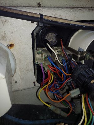
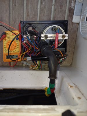
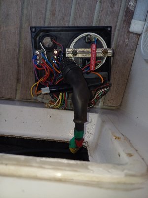
Well I'm baffled...last year now and again the engine wouldn't shut down , if I wiggled the switch up and down it would eventually shut down . Easy I thought, fit a new switch, now fitted, no difference, won't shut down . This is a panel with the left switch does glow and test the right switch does shutdown - off - ignition on. I've replaced both switches and both relays in the MDI box although I'm not sure it's the original as the start relay is out side the box . I've traced the wire from the panel to the shut off solenoid and got continuity. On the back of the switch with 6 terminals 4 are connected 3 one side one and one in the middle pole, which is the shutoff violet wire on the other side. However when operated no current is getting to the violet wire. I took a photo before I replaced it so I know the wires are right. Not sure of the nxt step. HELP PLEASE...