repairing a damage membrane switch

Ian_Edwards

Well-Known Member
Joined
9 Feb 2002
Messages
2,227
Location
Aberdeen Scotland
Visit site
Hi,
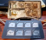
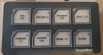
The membrane switch at the port helm has failed, this is the 3rd one to fail.
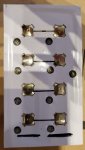
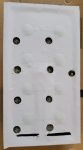
So I decided to take the top layer off and have look.
It's obvious that water has penetrated and got to the metal contacts.
I plan to clean all the old plastic of, probably with a sharp scalpel, and then test the contacts with a multi meter to ensure that the still work. They look fairly clean, so I think that I'm in with chance of getting the switches to work.

I'll then need to cover the face with a new "plastic" sheet or sheets. I'll probably try with 2 sheets, white to cover the switches, which I can mark the functions on and then a clear one on top as protection.

Questions:

1) what type of plastic should I use?
2) how thick should it be? It obviously has to be thin enough to allow the membrane switches to operate, but thick enough to provide protection.
3) what would be the best adhesive to use?
 

Attachments

  • damaged membrain -1.jpg
    damaged membrain -1.jpg
    56.1 KB · Views: 0
These are a nightmare, I have a couple of systems on the tugs I work on that used to use similar membrane buttons. I ended up making panels and using physical push buttons... not always possible, depending if you can modify circuit boards.

Nothing worse than a bored operative... they start picking at the buttons!!
 
Yes, I agree they are a nightmare, these got water in them, in essence because they weren't sealed properly.
I can't easily replace them with push button switches, they connect to a CANBUS interface which is completely encapsulated in epoxy, repair is the only option (other than an expensive 4th replacement)
I've been researching the university of YouTube and I have cunning plan, now I understand the principle behind their construction.
 
Re: repairing a damage membrane switch - UPDATE

After opening up the switch panel, I carefully cleaned both the flexible top layer and the base PCB with a scalpel blade and then IPA.
It was clear that there was no damaged to the PCB or the switch buttons, both were clean with no sign of corrosion.
My research on the internet suggested that the buttons need a former to hold the buttons over the pads on the PCB, after a little trial and error, I discovered that self-adhesive vinyl might work, but a single sheet was too thin to locate the buttons, so I laminated 4 sheets together.
I then scanned the PCB and printed a template, and after 3 attempts to get the scaling correct, I used the printed scan as a template to cut recesses onto the vinyl, to hold the button in place. I also cut channels between adjacent recesses, to give the air, which is compressed when the button is pressed somewhere to expand into.
I'm not sure that this is strictly necessary, but it seems to be common practice in commercially manufactured membrane switches.
The circular holes are to allow the LEDs which indicate if the function is on, or that there is a fault, to shine through and they where cut using a 6mm hole punch.
I then covered the switches with a single layer of self-adhesive vinyl, to hold everything in place. It was quite hard to line the holes up without getting the adhesive on the vinyl stuck and "relocating" the buttons.
Finally I refitted the top cover, although I've not glued that in place as yet, I want to see if the membrane switch panel works when I'm next on the boat (next week) before I use 2 part polyurethane glue to stick the whole lot back together.
I didn't incorporate an electromagnetic shielding layer, which seems common on commercial membrane switches, none of the switch functions are that critical and I don't think the boat is a high EMI environment.
photos, top line left to right: PCB after being cleaned up; front cover after cleaning; photocopy of the PCB used as a template.
Second line, left to right: new former with the button in place; vinyl cover in place, top cover reassembled
 

Attachments

  • Base circuit board.jpg
    Base circuit board.jpg
    53 KB · Views: 0
  • front cover.jpg
    front cover.jpg
    47 KB · Views: 0
  • Scanned PCB.jpg
    Scanned PCB.jpg
    54.9 KB · Views: 0
  • Trial fit.jpg
    Trial fit.jpg
    29.5 KB · Views: 0
  • Top layer of Vinyl.jpg
    Top layer of Vinyl.jpg
    18.7 KB · Views: 0
  • back together.jpg
    back together.jpg
    32.5 KB · Views: 0
Last edited:
Top