Play in the steering system.

Yeoman_24

Member
Joined
15 Jun 2014
Messages
176
Location
Gloucestershire
Visit site
My Moody 30 has a Whitlock, Cobra 3 steering system. I had some play in the steering so last winter completely overhauled the mechanism within the pedestal. Over the summer, some slack returned.

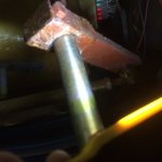
I have looked at the rudder end of the steering mechanism and attach a picture.

The stainless pole, top to bottom, is the rudder ‘pole’. The rusty cross-arm clamped to it goes across to a rose joint’ which attaches to the horizontal bar which runs off to the left of the picture to the base of the steering binnacle.

There is a rusty feather / quadrant key which is visible.

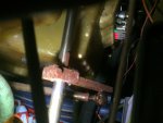
I think water has run down the ‘rudder pole’, rusted the cross-arm which has in turn lost its grip and dropped down slightly. I reckon the top of the groove in the cross-arm is in the lower end curve of the key which is causing the play. Hope that makes sense?

(Pic 2 is from below showing groove in cross-arm)

Any thoughts or experience would be great please.
1BB2441C-C10B-40C1-BA94-7D31CCEBA72A.jpeg 22B97555-E87C-4E78-9FE4-3EF57F84515E.jpeg
 
Last edited:

Quandary

Well-known member
Joined
20 Mar 2008
Messages
8,204
Location
Argyll
Visit site
There used to be an exploded diagram on the Sigma 38 website but that was a long time ago. However if you Google 'Whitlock Cobra Steering' you will be offered a maintenance manual to download, might that help?
 

captainboo

Active member
Joined
11 Dec 2008
Messages
486
Location
Near Glasgow
Visit site
I have the same system and have also overhauled mine in the past. The 'rusty' arm should be clamped to the shaft by way of the pinch bolt whose head you can see in the pictures. Once tight it should not move at all and have no play around the key.

When you originally overhauled it did you adjust the backlash between the input pinion and the crown wheel by means of shims between the pinion housing and the pedestal?

Have you got any wear in the rose joints?
 

rudolph_hart

Active member
Joined
23 Oct 2003
Messages
1,376
Location
Maldon, East Coast UK
Visit site
In Photo 2, it does look like there is void area at the bottom of the keyway on the underside of the rusty arm.

However, before loosening it to tap it upwards, I'd check the 'end stop' which is bolted to the underside of the cockpit sole (it's the L-bracket visible on the far left of the photo). When on full lock, if the rusty arm touches it close to the bottom, then this might indicate the rusty arm has slipped down. When moving it up again, I'd stop when the bottom of the key can be seen. I'd also use a few cable ties on the wires near the back of the engine control panel, to avoid fouling on the end of the rusty arm :(

Hope this helps
 

Birdseye

Well-known member
Joined
9 Mar 2003
Messages
28,162
Location
s e wales
Visit site
I have the same system and have also overhauled mine in the past. The 'rusty' arm should be clamped to the shaft by way of the pinch bolt whose head you can see in the pictures. Once tight it should not move at all and have no play around the key.

When you originally overhauled it did you adjust the backlash between the input pinion and the crown wheel by means of shims between the pinion housing and the pedestal?

Have you got any wear in the rose joints?

That would be my first thought, but in any case if you have play where the arm fastens onto the rudder shaft it should be obvious if you stick your head in the area concerned and get someone to waggle the steering for you. If you have play there then it should be easy enugh to shim up the key at the arm end

If it is neither of those then my system has some slack in the rose joints. There is supposed to be a nylon lining between ball and socket but it wears and drops out over time.

Last issue - could the shaft be moving inside the rudder itself?
 

Yeoman_24

Member
Joined
15 Jun 2014
Messages
176
Location
Gloucestershire
Visit site
When you originally overhauled it did you adjust the backlash between the input pinion and the crown wheel by means of shims between the pinion housing and the pedestal?
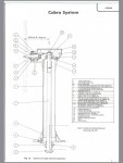
I’ve attached an exploded view of the cobra 3 pedestal. I replaced the quadrant key (item 11a) as it was obvious that was corroded and where the play at that end was. Not sure where and exactly what you are describing. Perhaps the pic will be useful to help me understand.
I’ll have a much closer look at the rose joints.
A48F026B-108D-4B3C-9AFA-D6280A564DD0.jpg
 

Yeoman_24

Member
Joined
15 Jun 2014
Messages
176
Location
Gloucestershire
Visit site
I'd check the 'end stop' which is bolted to the underside of the cockpit sole (it's the L-bracket visible on the far left of the photo). When on full lock, if the rusty arm touches it close to the bottom, then this might indicate the rusty arm has slipped down.

That would be a useful reference point to indicate or confirm a slip down. Good shout, and the cable ties suggestion! Cheers
 

Yeoman_24

Member
Joined
15 Jun 2014
Messages
176
Location
Gloucestershire
Visit site
If it is neither of those then my system has some slack in the rose joints. There is supposed to be a nylon lining between ball and socket but it wears and drops out over time.

Last issue - could the shaft be moving inside the rudder itself?

Last issue - hadn’t considered that. Bugger. Good shout though ta.
 

Yeoman_24

Member
Joined
15 Jun 2014
Messages
176
Location
Gloucestershire
Visit site
...... and having done some more research on my 1977 Moody 30, and having looked at the pics again in more detail I think I may have automotive track rod ends rather than rose joints!?!?
Informed thoughts and observations are very welcome please!!
 

captainboo

Active member
Joined
11 Dec 2008
Messages
486
Location
Near Glasgow
Visit site
I’ve attached an exploded view of the cobra 3 pedestal. I replaced the quadrant key (item 11a) as it was obvious that was corroded and where the play at that end was. Not sure where and exactly what you are describing. Perhaps the pic will be useful to help me understand.
I’ll have a much closer look at the rose joints.
View attachment 75521

If you look at the attached link for more information it describes the process for 'Reshimming the pedestal to adjust gear mesh'

http://www.eddievan.com/documents/whitlock_cobra_steering.pdf

These can be seen in the exploded diagram on page 2 - the three thin discs below the letter 'L'.
 
Last edited:
Top