BabaYaga
Well-known member
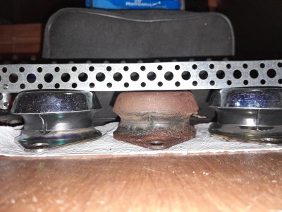
After 18 years I am replacing the engine feet on my 20 hp Beta engine.
The original feet were made by Trelleborg, the replacements (bought from a Beta representative) are by AMC Mecanocaucho and slightly higher.
As can be seen in the photo, in my installation there is very little thread left on the height adjuster pin under the adjustment nut, in other words the engine bracket sits very low on the pin.
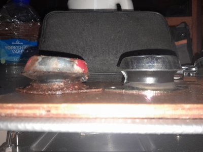
The replacement foot (to the right in the photo for comparison) has nyloc nuts both for height adjustment and for locking (so on both sides of the engine bracket), unlike the original, that has a nyloc nut only on the upper side of the bracket, for locking.
In order to be able to use the replacement feet, I am thinking of doing away with the lower, height adjusting nyloc nut, replacing it with a thinner, plain nut, similar the the one that is used to lock the pin to the anti vibration unit. The thread on the pin is M16 and a low profile nut would be 7-8mm thick.
Does anyone see any problem with this approach?
TIA

The original feet were made by Trelleborg, the replacements (bought from a Beta representative) are by AMC Mecanocaucho and slightly higher.
As can be seen in the photo, in my installation there is very little thread left on the height adjuster pin under the adjustment nut, in other words the engine bracket sits very low on the pin.
The replacement foot (to the right in the photo for comparison) has nyloc nuts both for height adjustment and for locking (so on both sides of the engine bracket), unlike the original, that has a nyloc nut only on the upper side of the bracket, for locking.
In order to be able to use the replacement feet, I am thinking of doing away with the lower, height adjusting nyloc nut, replacing it with a thinner, plain nut, similar the the one that is used to lock the pin to the anti vibration unit. The thread on the pin is M16 and a low profile nut would be 7-8mm thick.
Does anyone see any problem with this approach?
TIA
 I bet they are all a bit "Wobbly" after 18 years