Issues when trying to expand Solar array

Duncancw

Member
Joined
12 Feb 2021
Messages
41
Visit site
Hi,
My boat currently has a 90Watt solar system that provides power to the house battery. It's great for keeping the battery topped up in winter when she is ashore and during the summer it does keep my 12v fridge running most of the day (in sunny conditions). It's great for day sailing and the weekends but not great if we want to use the boat for an extended period as it doesn't generate enough power.

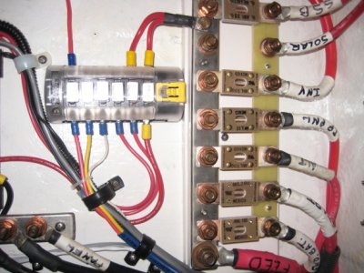
I've recently purchased an additional 200watts of solar (2x100watt panels in serial). I've installed the panels and ran the cables to a new Victron SCC (100/20). The bit I'm having problems with the connection between the new SCC and the house battery. The existing system is getting very messy and there are already 5 connections on the positive side of the house battery. I really like to find a better solution for this. The other problem is that the existing SCC is using the main posts on that 6 way circuit fuse panel, i.e only allowing me to use one circuit and thus I can't connect the new SCC to the fuse panel.

I've attached a diagram to illustrate my scenario. The new components in the gold box are what I've install but I've not attached them to anything yet. (I haven't actually wired the new solar panels into the SCC but the cables are in situ).

Should I get rid of the 6 way fuse box and install a Victron fused distribution board or is that overkill? or could I just install a positive busbar or can I make use of the 6 way fuse box?

Any advise before I proceed any further would be greatly appreciated.

Attachments​


Attachments

  • Solar Panels update.pdf
    271.6 KB · Views: 21

geem

Well-known member
Joined
27 Apr 2006
Messages
7,786
Location
Caribbean
Visit site
You should only have one connection on the battery terminal which should go to an unswitched positive distribution bus bar and then to a switch and then to your switched panel. All your unswitched loads and supplies can go to the bus. Then they can be labeled and tidy.
Ideally you isolate the battery in its entirety with an isolator. You then go from the isolator to a busbar. The maximum recommended number of terminals on any power post is 3. You could connect the solar regulator direct to the battery terminals if you use the isolator to turn everything off when you leave the boat.
 

pmagowan

Well-known member
Joined
7 Sep 2009
Messages
11,793
Location
Northern Ireland
sites.google.com
Well, there are unswitched loads etc that should be before the main switch. Eg bilge pumps etc. these are the things people attach directly to the battery terminal making things messy when they should be on the unswitched bus bar. The isolator switch then isolates the battery from all other loads etc
 

geem

Well-known member
Joined
27 Apr 2006
Messages
7,786
Location
Caribbean
Visit site
Well, there are unswitched loads etc that should be before the main switch. Eg bilge pumps etc. these are the things people attach directly to the battery terminal making things messy when they should be on the unswitched bus bar. The isolator switch then isolates the battery from all other loads etc
Why not just leave everything on if you need the bilge pump to work? You can isolate everything else at the main panel if you want to. In my head, a battery isolator should do just that. Isolate the battery
 

noelex

Well-known member
Joined
2 Jul 2005
Messages
4,629
Visit site
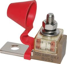
I would install a positive busbar and attach the solar output to this. You will need a fuse. An MRBF fuse can be a neat way to add a fused connection that works well on some larger busbars, but there are plenty of other alternatives.

For more money you could use a Lynx Distributor, which is basically a (+ and - ) busbar with fused outputs, but with only 4 outputs as standard. You can also modify a Lynx Power In to become almost a Lynx Distributor for less cost.

There is also the possibility of constructing your own busbars with a fused output, such as the example below (not my photo).

There are many options, above is only a few of the alternatives, but hopefully one of these ideas will be suitable.

IMG_6960.jpeg
 
Last edited:

pmagowan

Well-known member
Joined
7 Sep 2009
Messages
11,793
Location
Northern Ireland
sites.google.com
Why not just leave everything on if you need the bilge pump to work? You can isolate everything else at the main panel if you want to. In my head, a battery isolator should do just that. Isolate the battery
When designing a system it is always best to take the human element out of safety critical parts. If you provide a switch it is only a matter of time before it is switched off and bilge pumps etc are not working. There are a number of wires that should go directly to the battery and with no unswitched bus bar that is where they end, making a mess
 

oldmanofthehills

Well-known member
Joined
13 Aug 2010
Messages
4,945
Location
Bristol / Cornwall
Visit site
I agree with pmagowan

We have feed to main auto bilge pump, gas detector and ebispacher, and feed from inbuilt battery charger, direct to leisure battery. We certainly dont want pump or detector turned off in error (Ebi feed is not ideal but due to current capacity issue in isolator)

Everything else goes via isolator switch to the distribution panel and or related fuses.
 
Last edited:

B27

Well-known member
Joined
26 Jul 2023
Messages
1,790
Visit site
Do you want your 'big switch' to be a 'main switch' or a 'battery isolator'?

There are a few permutations of wiring things around switches and VSRs etc, each has pro's and con's, perhaps the main thing is to know what you've got?

Some 'unswitched' bus bars look like big areas of unfused +12V to me.

The best way to connect things together will often be influenced by physical layout, so would vary from boat to boat.

I have two connections to my house battery +ve, one high current wire which goes to the 1B2 switch and a medium wire going to a small fuse box, which serves solar input and unswitched output.
 

noelex

Well-known member
Joined
2 Jul 2005
Messages
4,629
Visit site
I have owned boats with an essential supply circuit, sometimes called "always on" (so the main battery switch does not shut off all circuits) and boats without this feature. Both systems have advantages and drawbacks, but both can work well.

It is obviously essential to understand which system is installed on your boat, and of course all systems should be adequately fused.
 
Last edited:

Duncancw

Member
Joined
12 Feb 2021
Messages
41
Visit site
Hi
Thanks to everyone for your replies.

Based on the feedback, I've put together this updated diagram. The new positive busbar will support the new and existing solar systems and mitigate the messy positive terminal on the house battery as I will migrate the pi and the BMV cable onto the same busbar. I have some spare 4 AWG cable that will support up to 85amps. I will use this to connect from the positive terminal on the battery to the new positive busbar. I was thinking that i should also install a neg busbar to consolidate the negative cables from the solar systems (maybe a little overkill?)

I've fused both solar systems between the MPPT's and the battery.

I appreciate that I still have three connections on the positive terminal of the battery ( switched circuit, alternator, and the new positive unswitched busbar). However, that feels a lot less messy. The big question is will this design work?
 

Attachments

  • Solar Panels with busbar.pdf
    241.8 KB · Views: 8

pmagowan

Well-known member
Joined
7 Sep 2009
Messages
11,793
Location
Northern Ireland
sites.google.com
On the positive terminal of the battery you can put a large fuse that looks like this: 1723117029752.png
You take a single cable to a heavy bus bar (unswitched) then from the bus bar to your switch, then from switch to panel.
One cable on battery fuse terminal. Everything on the unswitched bus bar should have an inline fuse of appropriate rating to the wire. Fuse on battery should have appropriate rating to protect the cable used to the bus bar and panel. The panel will obviously have fuses or MCBs of appropriate rating to protect the wire of connected loads also.
 

B27

Well-known member
Joined
26 Jul 2023
Messages
1,790
Visit site
Your shunt looks to be shorted by a bus bar?
Is the wiring stout enough to blow that 125A fuse in the main panel feed? How big does that fuse need to be?
As above, the small lines from the + bus bar should be fused.

Beware of subtle connections which defeat the battery isolator, like signal returns to the Pi, data wiring to the MPPT or anything
 

B27

Well-known member
Joined
26 Jul 2023
Messages
1,790
Visit site
Why do you choose to put the switch on the negative side?
I think it's the same logic as disconnecting the earth terminal first when removing a car battery?

It doesn't make much sense when there's an 'always on' circuit IMHO.

Does it create issues with 230V wiring, where it's connected to some DC GND but not all?
 

pmagowan

Well-known member
Joined
7 Sep 2009
Messages
11,793
Location
Northern Ireland
sites.google.com
Where a boat has lots of earth/negative terminal kicking around I would want my switch in the positive, immediately after the un-switched bus. Otherwise when you turn things 'off', which people will assume means no positive connection, they will still be 'live' with respect to many areas of the boat such as the engine block or anything else bonded. Irrespective of whether it is electrons flowing or electron holes or even electromagnetic fields I think most people think of positive to negative therefore switch in positive to break before wiring.
 

Duncancw

Member
Joined
12 Feb 2021
Messages
41
Visit site
Your shunt looks to be shorted by a bus bar?
Is the wiring stout enough to blow that 125A fuse in the main panel feed? How big does that fuse need to be?
As above, the small lines from the + bus bar should be fused.

Beware of subtle connections which defeat the battery isolator, like signal returns to the Pi, data wiring to the MPPT or anything
Good spot, totally agree, don't know why I put a connection between the neg on the battery and the new neg busbar. The only reason for the new negative busbar is to consolidate the two negative cables that come from the two separate MPPT's. They need to go to the the other side of the shunt and I just didn't want additional connections on the shunt. As mentioned on previous post don't know if the new neg busbar is overkill and I should just run the additional cable to the shunt?

All the wiring and the fuse that feeds to the main panel has been installed when the boat was originally built (by Bavaria).

My logic for not putting a heavy duty positive busbar and connecting everything to that busbar including the existing circuit that feeds the main panel and the alternator, is that I was concerned that the addition of the MPPT's might overload the main circuit. Would you recommend purchasing a heavy duty busbar and going down that route or keeping it separate as per the current design?

In my first post, (the original diagram attached) mentions that the small cable that feeds the Pi is actually there just to an additional cable that allows the Pi to shutdown gracefully if it is switch off at the main panel (were it is fused)

Re your comment about "beware of subtle connections which defeat the battery isolator". My thought process is that everything that is connected to the unswitched busbars won't be effected by the battery isolator, i.e. they are always on, unless the circuit is broken (fused). Is my thinking not correct?

Thanks for your advise, much appreciated.

I've attached a new diagram with the connection from the battery to the new neg bus bar removed.
 

Attachments

  • Solar Panels with busbar.pdf
    241.7 KB · Views: 3
Last edited:

B27

Well-known member
Joined
26 Jul 2023
Messages
1,790
Visit site
If you have a shore power charger, and it's always on, then how is it earthed?
Are there and data cables between the Victron kit? Beware of screen connections which could be 'always on 0V', so must be isolated from 'boat earth'.

Earthing on boats with shore power is not a trivial subject.
 

pmagowan

Well-known member
Joined
7 Sep 2009
Messages
11,793
Location
Northern Ireland
sites.google.com
You only need a bus bar if you have lots of connections. You can make up to 3 or 4 connections to a single terminal. You risk bad connections if you stack too many.
I don't understand why you would have any other connections to the battery positive terminal. That is the purpose of the (currently empty) positive bus bar. I, personally, would move the switch to the positive side. Someone, at some stage, will make an earth connection which bypasses the switch if on the negative side. People don't respect the black wires the same as the red ones.
I think your current setup is very confusing to anyone trying ,including yourself, to problem solve. Eg, although there is a switch in the circuit with the lower left bus bar since the switch is in the negative side that bus bar can be considered unswitched. It is identical to the positive terminal of the battery and is at 12V potential. It only becomes 'switched' if the negative wire is attached somewhere prior to your switch. I.e. everything is back to front from how anyone would normally do it and how most peoples brains think. Someone making a positive connection here and a negative connection on the unswtched side, or to the engine, or the shunt, or the battery negative terminal (whichever is convenient) will have a permanent unswitched load bypassing your switch.

Not saying your system isn't possible but you just need to always think back to front of how it is done on almost every other boat.
 
Top