Help with NMEA wiring diagram - Please!

RichardS

N/A
Joined
5 Nov 2009
Messages
29,212
Location
Home UK Midlands / Boat Croatia
Visit site
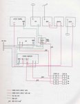
I have attached the systems wiring diagram for my boat as it doesn't make sense to me.

The box entitled "Course Computor" is my Raymarine C80 Classic chartplotter. It has NMEA, and two Seatalk ports. The manual shows that the NMEA port has 4 connections: NMEA Output +ve and -ve (common) and NMEA Input +ve and -ve (common).

The diagram shows an NMEA cable going to the DSC VHF radio. The cable is marked with two small arrows pointing out of the C80 and two small arrows going into the VHF.

I have removed the VHF and there are only two NMEA wires connected from the harness to the VHF, a red wire and a blue wire. However, there are 4 NMEA wires coming out of the back of the VHF: Gray NMEA IN +ve, Purple NMEA IN -ve, (both labelled as GPS) and Blue NMEA OUT +ve, Brown NMEA OUT -ve (both labelled as Chartplotter Display). I understand that the chartplotter connection is so the plotter can display the position of a DSC distress call which is sent by the VHF.

The 4 wires coming out of the VHF are twisted together into 2 pairs: Grey and Blue (NMEA IN +ve and NMEA OUT +ve) are twisted and connected to the red harness cable and Brown and Purple (NMEA OUT -ve and NMEA IN -ve) are twisted and connected to the blue harness cable.

I was thinking of connecting the NMEA output of my AIS unit to the red and blue harness cables to see if I can get the C80 to display the AIS data because the AIS receiver is located next to the VHF so the wiring is convenient.

I appreciate that without a multiplexer I would have to leave the VHF NMEA cables disconnected and change the NMEA input of the C80 to 38,400 but I am confused as to how the red and blue wires appear to carry data in both directions as is suggested by the fact the the input and output to the VHF seem to use only the 2 wires.

Can NMEA operate in both directions over two cables or I am misunderstanding the twisting together of the VHF NMEA wires?

Many thanks

Richard
 

Attachments

  • NMEA-Wiring-Diagram.jpg
    NMEA-Wiring-Diagram.jpg
    47.2 KB · Views: 17
If I've understood your description correctly, the NMEA in and out wires should not be twisted together into one connection. That does not make sense to me and I would have thought it might cause some operational problems. I suspect the NMEA wires are balanced so the -'ve are not connected to ground in the conventional sense. NMEA is not bidirectional - it cannot share a wire for receive and transmit.

Basically, you need to connect the NMEA out wires of the chartplotter onto the NMEA in wires of the VHF. This will pass the GPS position data to the VHF so that it can transmit your position. You then need to connect the NMEA in wires of the chartplotter onto the NMEA out wires of the VHF. This will allow the VHF to pass and DSC call data to the plotter. This port on the plotter will need to be set to 38400 to operate correctly. Each NMEA out can ussually supply data to up to 3 receiving devices.
 
Last edited:
If I've understood your description correctly, the NMEA in and out wires should not be twisted together into one connection. That does not make sense to me and I would have thought it might cause some operational problems. I suspect the NMEA wires are balanced so the -'ve are not connected to ground in the conventional sense. NMEA is not bidirectional - it cannot share a wire for receive and transmit.

Many thanks Keith. You have understood correctly. The current odd arrangement does not seem to cause any problems although I've never received a distress call but I assume that it's not going to show up on the plotter as you say that NMEA is not bidirectional.

It looks as if I need to run NMEA in wires from the chartplotter through to where the VHF is. These wires are not present in the harness next to the VHF at the moment. Maybe the plotter in-wires run to the NMEA Junction Box to pick up the GPS signal? I'll see if I can find this Junction Box.

Richard
 
I have removed the VHF and there are only two NMEA wires connected from the harness to the VHF, a red wire and a blue wire. However, there are 4 NMEA wires coming out of the back of the VHF: Gray NMEA IN +ve, Purple NMEA IN -ve, (both labelled as GPS) and Blue NMEA OUT +ve, Brown NMEA OUT -ve (both labelled as Chartplotter Display). I understand that the chartplotter connection is so the plotter can display the position of a DSC distress call which is sent by the VHF.

The 4 wires coming out of the VHF are twisted together into 2 pairs: Grey and Blue (NMEA IN +ve and NMEA OUT +ve) are twisted and connected to the red harness cable and Brown and Purple (NMEA OUT -ve and NMEA IN -ve) are twisted and connected to the blue harness cable.

I can't see that this would work; do you see any DSC information on the plotter?

If you want to display AIS data on your plotter, you'll need to use a multiplexer to combine the GPS and AIS data inputs (as they run at different speeds).
 
... the NMEA in and out wires should not be twisted together into one connection...
Basically, you need to connect the NMEA out wires of the chartplotter onto the NMEA in wires of the VHF... You then need to connect the NMEA in wires of the chartplotter onto the NMEA out wires of the VHF. ...

Exactly.

You can only use AIS if your plotter supports 38400 Baud.
 
The box entitled "Course Computor" is my Raymarine C80 Classic chartplotter.

Are you sure of that?

Why then is it labelled Course Comput[e]r? Or has the boat's system been altered since the diagram (which looks rather old) was drawn?

Where is the course computer now connected? Or is your autopilot an ST4000 where the computer and controller are one and the same?

I appreciate that without a multiplexer I would have to leave the VHF NMEA cables disconnected and change the NMEA input of the C80 to 38,400

Isn't the NMEA input already being used for the GPS position info? That's what your diagram says (if we accept your idea that the "Course Computor" box is actually the plotter).

Pete
 
Are you sure of that?

Why then is it labelled Course Comput[e]r? Or has the boat's system been altered since the diagram (which looks rather old) was drawn?

Where is the course computer now connected? Or is your autopilot an ST4000 where the computer and controller are one and the same?

Isn't the NMEA input already being used for the GPS position info? That's what your diagram says (if we accept your idea that the "Course Computor" box is actually the plotter).

Pete

Good grief - you may well be correct Pete. I was looking for something in the various manuals that had one NMEA 0183 connection and two Seatalk connections like the box labelled "course computor" on the schematic and that looked like the C80. I didn't look at the autopilot hardware manual which is a Raymarine Smartpilot S3! It even says "Course Computer" on the lid but I've never noticed that before!

The S3 seems to have two NMEA 0183 connectors and two Seatalk connectors but I guess that one is not used so it doesn't appear on the schematic.

I apologise that I'm so slow with this. It's all totally new to me, as you can guess!

OK, where on the schematic is the C80 plotter do you think? Is it the box labelled "Graphic"? If so, the NMEA 0183 connector does not appear to be used at all so I could run a cable over to where the AIS unit is and set the C80 to 38,400 and display the AIS data.

It seems clear from what you guys have explained that I cannot use the convenient red and blue wires which run to the VHF as these must be inputting position data into the VHF for the DSC and therefore I cannot use them for the NMEA output from the AIS unit.

It's painful but with help from you guys I think I'm getting there slowly.

Richard
 
OK, where on the schematic is the C80 plotter do you think? Is it the box labelled "Graphic"?

It's not on there. Must have been added since that diagram was drawn up. The Graphic is a 4" instrument like Wind or Depth but with a more flexible display that can show a variety of data, and the fact that the corresponding box is connected only to Seatalk and located next to the other instruments reinforces that explanation.

If your NMEA GPS data is getting into the Seatalk system via the course computer, then you should have a free input port on the back of the plotter for the AIS data, which is good.

Pete
 
I've only just noticed this bit:

The 4 wires coming out of the VHF are twisted together into 2 pairs: Grey and Blue (NMEA IN +ve and NMEA OUT +ve) are twisted and connected to the red harness cable and Brown and Purple (NMEA OUT -ve and NMEA IN -ve) are twisted and connected to the blue harness cable.

This is completely wrong and stupid. Any time the VHF tries to output anything, it's going to stomp all over its own incoming data.

I guess it mostly works because the VHF only emits anything when it receives a DSC distress call, and that's quite rare.

Pete
 
Richard

Its hard to advise you when we cant see what you have in detail. Its better that you go back to first principles and work it through yourself because it really is straightforward.

Your C80 classic will only operate at one baud speed. So if you alter the setting to take the i9nput from an AIS at 38400 then the output of the C80 will also be 38400 and like as not your VHF and pilot wont like it.

All SRC VHF radios will take an NMEA input but most dont send out an NMEA signal mif they receive a mayday. If your radio does not have two output NMEA wires as well as the two inpout ones I very much doubt that it will give out an NMEA position sentence if it receives an emergency call.

Your wiring diagram doesnt show the C80. It only shows the course computer for the autopilot which is a seperate box of tricks that controls the pilot.

That apart the circuitry should be simple. Your C80 has 4 NMEA wires, 2 in and 2 out. Do you have any gadget that needs to send an NMEA signal to the plotter? From your post it looks as if the AIS is the only one, assuming that your GPS is a Raymarine one that talks seatalk.. As for the NMEA output from the plotter that needs to go to the VHF, and by the look of it your pilot computer. You can certainly connect two listeners in parallel.

If you want to use ais then you will need a multiplexer. Try Brookhouse in NZ - I got very good service from them and they give technical advice by email.
 
Its hard to advise you when we cant see what you have in detail. Its better that you go back to first principles and work it through yourself because it really is straightforward.

I certainly agree with that, but...

the output of the C80 will also be 38400 and like as not your VHF and pilot wont like it.

The pilot is (or should be) connected via Seatalk, so NMEA bitrate is irrelevant. There's no reason to take the VHF's position data via the C80 - it's just a plotter, not a GPS, so it would only be passing it through from elsewhere.

All SRC VHF radios will take an NMEA input but most dont send out an NMEA signal mif they receive a mayday.

The OP's does though, he told us it has an NMEA out wire (of course, he may not be interested in using this feature).

assuming that your GPS is a Raymarine one that talks seatalk.

It's not, it's shown on the diagram connected via NMEA.

As for the NMEA output from the plotter that needs to go to the VHF

No - the output from the GPS can go to the VHF and into an NMEA input somewhere on the Raymarine kit.

If you want to use ais then you will need a multiplexer.

The GPS position is currently getting into the Raymarine world via the NMEA input on the course computer. This leaves the port on the plotter free for AIS with no multiplexer required. As long as he doesn't want to connect up the VHF output wires, that is, which seems a reasonable tradeoff. Does anyone know if the C80 even does anything useful with DSC messages?

Pete
 
Last edited:
Thanks to you all - that's very helpful.

Next time I am on the boat I clearly need to have a look at the back of the C80 and see exactly which of its ports are in use.

From the manual the C80 appears to have one NMEA 0183 input/output port (4 pins + gnd), one Seatalk port (3 pins) and one Seatalk2 port (5 pins). If nothing is currently connected to the NMEA port, I think the manual says that I can configure it at 38,400 without affecting the Seatalk ports. I could then use it for inputting AIS without a multiplexer.

The wiring diagram is obviously not very helpful after all!

Edit - just seen your post Pete and I think you have hit all the nails on their heads! I now need to get me hands a bit dirty!

Richard
 
Last edited:
The GPS position is currently getting into the Raymarine world via the NMEA input on the course computer. This leaves the port on the plotter free for AIS with no multiplexer required. As long as he doesn't want to connect up the VHF output wires, that is, which seems a reasonable tradeoff. Does anyone know if the C80 even does anything useful with DSC messages?

Yes, the C80 can display details of DSC messages on screen. I'm not sure that we do know how the GPS data is getting to the C80 - it may be going via SeaTalk, but equally it may be connected to the C80's NMEA socket (the OP hasn't said).
 
Yes, the C80 can display details of DSC messages on screen. I'm not sure that we do know how the GPS data is getting to the C80 - it may be going via SeaTalk, but equally it may be connected to the C80's NMEA socket (the OP hasn't said).

That's good to know pvb, but as several posters have pointed out, the NMEA output from my DSC VHF has been kludged together with the GPS input to the VHF so I think that its been nobbled wherever it wants to go. As Pete suggested, I can't see that this is ever going to be much use to me so I'll probably leave it as it is as it seems to work i.e. the VHF does get a GPS signal as it displays lat and long on its screen.

Richard

Edit - Having read Pete's reply to your post pvb I can see that I've misunderstood the main point you were making. Doh!
 
Last edited:
Yes, the C80 can display details of DSC messages on screen. I'm not sure that we do know how the GPS data is getting to the C80 - it may be going via SeaTalk, but equally it may be connected to the C80's NMEA socket (the OP hasn't said).

I suppose. But even if the same idiot who twisted the VHF input and output wires together also wired the GPS to the C80 NMEA port when he added the plotter, that can be simply disconnected because the C80 will be getting its position over Seatalk from the course computer. Unless the C80 isn't connected to seatalk at all, which is unlikely, stupid, and should be rectified if it turns out to be the case.

Pete
 
Last edited:
I'll probably leave it as it is as it seems to work i.e. the VHF does get a GPS signal as it displays lat and long on its screen.

It would be better to separate the NMEA output +ve and -ve and tape them up neatly out of the way, just to remove any potential for interference if the VHF does decide to output something.

Pete
 
I suppose. But even if the same idiot who twisted the VHF input and output wires together also wired the GPS to the C80 NMEA port when he added the plotter, that can be simply disconnected because the C80 will be getting its position over Seatalk from the course computer.

I'm not convinced that the S3 course computer bridges NMEA data on to SeaTalk.
 
This is completely wrong and stupid. Any time the VHF tries to output anything, it's going to stomp all over its own incoming data.

I guess it mostly works because the VHF only emits anything when it receives a DSC distress call, and that's quite rare.

It's obviously wrong, but I would have been surprised if there was any data stomping, so I tried it. Data got through on both lines with no errors for the short time of my test. Only the very slightest ripples in the shape of the waveform on the scope. RS-422 is pretty robust at the speeds and short distances we use it for on boats.
 
Top