Fuse board to Engine Ground?

If people like to struggle who am I to butt in.

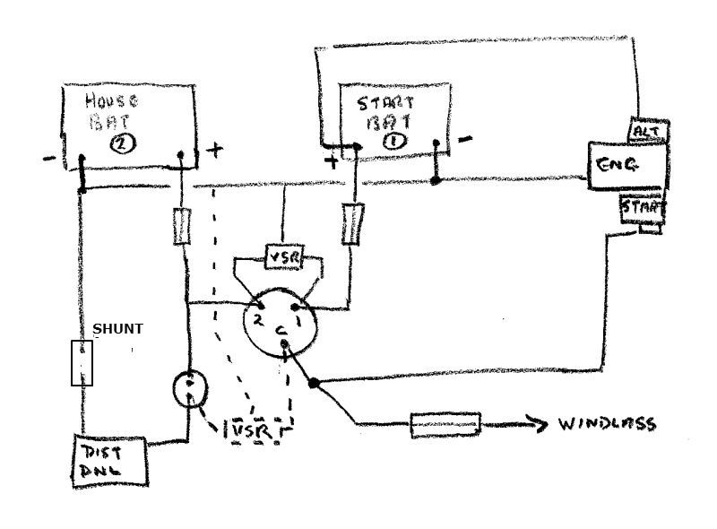
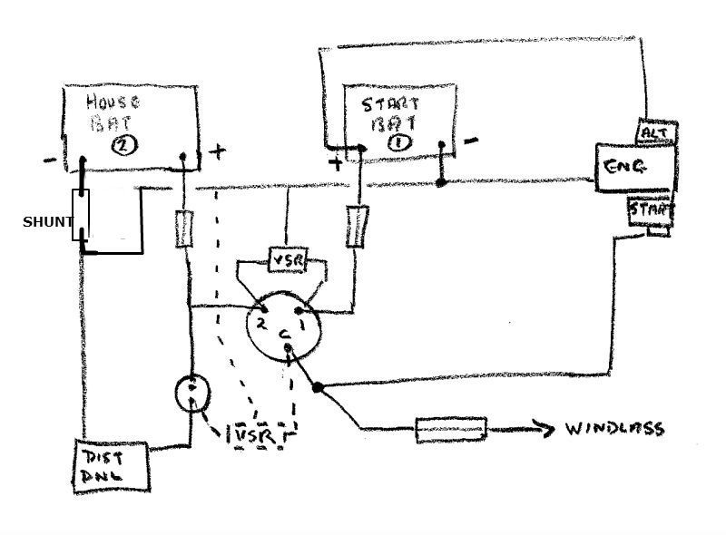
Note the ebay web site says it needs a separate power supply, so cannot us the same earth for meter and shunt. It needs a battery or isolated power supply to power the meter.

Brian


Hi Brian thanks for that, and I have all the components now as we went through all the business of isolated power supplies before on this thread, but nice of you to remind me.


http://www.ybw.com/forums/showthread.php?t=329775&highlight=ammeter+wiring

Having only just being able to get around to fitting this monitoring system, I have come up with some more queries, which people on the forum have been good enough to help me with.
I gave up on the previous idea of the switching arrangement having not being able to track down the switches? Having ordered two sets of switches from two different suppliers using the same catalogue part numbers, and being supplied with the wrong switches twice, I then rang ( Farnells who quoted twice the price of the other suppliers by the way ), who told me he could not guarantee the switches would be as described? He suggested that there may have been an incorrectly labeled Import from the manufacturers as it was the only way he could account for so many switches of the wrong sort being distributed under the correct catalogue numbers? When asked if he could check their stock to see if theirs were the correct switch as cataloged, he said they could only supply them and try and sort any problems out later?
Having got 4 switches of the wrong sort with the correct part numbers already, it was at this stage I decided to give up on the idea of monitoring two sources from one gauge as suggested by others, and settled on one bank of batteries, that being the domestic set.
 
Having got 4 switches of the wrong sort with the correct part numbers already, it was at this stage I decided to give up on the idea of monitoring two sources from one gauge as suggested by others, and settled on one bank of batteries, that being the domestic set.

Sorry to hear your problems, should have said you needed them, I could have added them to one of our orders. They do get items packed wrong, normally when I'm desperate, they normally get the carrier to collect faulty ones or just scrap them and refund me.

You could look at altering your battery layout, connect alternator to service battery, start engine from other bank, and use both position to charge engine battery. You would need a new isolator for engine battery, but it would allow you to monitor net amps in to / out off service battery.

Brian
 
You could look at altering your battery layout, connect alternator to service battery, start engine from other bank, and use both position to charge engine battery. You would need a new isolator for engine battery, but it would allow you to monitor net amps in to / out off service battery.

Brian[/QUOTE]

That’s quite a good solution, would I need an extra engine isolator, only it would be isolated when switched to domestic 2 anyway wouldn't it?
My batteries are usually never completely turned off as I always leave a Vetus Gas monitor on in intermittent mode run from the domestic set. Solar panel helps keep charge levels up.

You are isolating the engine from the battery, if you have solar panel, you could leave the batteries on both, switch to service battery when on the boat. The 1,2, both switch feeds the domestic switch board, the engine feed is via the new isolator switch.

This gives you a dedicated engine battery, and Vic's diagram for shunt would apply.

Brian
 
Wiring update

Hi Vyv,
Thanks for your input, Just thought I would mention that my 2Gm20 is not isolated earth reurn,somebody must have changed it, as all the senders on the engine are single power feeds with the earth coming from the engine, as Fisherman describes in the next post from yours.I don't know if this makes any difference to your explanation? The negative feed to the ammeter is indeed supplied from the fuse board so will actually feed through the shunt fitted between the Dis / Brd and the engine ground.So may pick up the alternator charge, but my alternator earth is the same as you said in your last sentance, earthed to the block so it may not measure the charge?

I think the only thing to do is give it a try and see what happends?

Will post the results when I have tried it


Fitted gauge to wiring- which was described previously, and thought I would post results.

Gauge measuring range -50amp - + 50amp

When first fitted as per wiring diagram from manufacturer, gauge showed 00.1 on discharge with galley light on, so changed the sensing wires over. Gauge then reads -00.1.
With no discharge at all gauge reads -00.0.
In my ignorance, I thought the gauge when turned on would read 0.00? Then when a discharge was present it would read - 00.? Depending on the amount.
As suggested by others previously no charging current was registered with engine running, even though it charged the battery right up to ( 100% Smartguage ).
On trying to sort out the negative to ground issue re the shunt I have discovered that the neg feed to the Fused distribution board does not go to the engine ground as first thought? But does actually go to the engine battery Negative?
It would appear that I have more of a wiring job to do than I originally thought, so it will have to wait until the new year when I can sort it all out.
2 years on from buying the boat, it’s not till you start adding things on that you realize just what wiring issue you may have? Especially when everything is working ok at the time?

Thanks to everybody for their input and will update again in the New Year.

Happy Christmas to all, Fair Winds for 2013

Philip
 
On trying to sort out the negative to ground issue re the shunt I have discovered that the neg feed to the Fused distribution board does not go to the engine ground as first thought? But does actually go to the engine battery Negative?

That does not matter. The battery negs and engine block are all connected together if I understand you correctly. Hopefully heavy battery cable used for all except the connection to the fuse board which you say is 6mm²

Connecting it to the domestic battery neg would have more logical than to the starter battery neg. I might have connected it to what you described earlier as a "negative distribution stud"
 
Fuse Board to Engine Ground - Update

That does not matter. The battery negs and engine block are all connected together if I understand you correctly. Hopefully heavy battery cable used for all except the connection to the fuse board which you say is 6mm²

Connecting it to the domestic battery neg would have more logical than to the starter battery neg. I might have connected it to what you described earlier as a "negative distribution stud"

Having now got a lot of the materials necessary to carry on with the rewire job for the ammeter I thought I would post this update of what I intend to do from the suggestions received on the site. I have decided to replace the 8mm Distribution board supply cable with 10m which should cope with up to 75amps which should be more than enough for my electronics etc, and makes it easier to terminate than 16mm.
One question I do have is about fuses. As the 1-2- both switch is now going to used as an isolator for the domestic battery side, and I am going to fit a separate engine battery isolator to separate the engine start circuit, would it be sensible to fit a 80amp Mega fuse on the 1-2-both switch distribution feed wire which will be connected to the common terminal, with the idea it will protect the domestic circuits when using the both facility to start the engine from the domestic battery. Also would it be a good idea to fit Mega fuses on the positive posts of the two batteries to protect each supply outlets .1 x windlass Fuse – 100amp, 1 x Engine Start- 175amp, ( would this be ok fitted to the same battery post?) 1 x domestic- 80amp.

Any thoughts on the wiring diagram posted please, and views on the fuse arrangements
 
Most important I think is that you show no means of charging the starter battery other than by paralleling with the house bank using the selector switch
I'd suggest a VSR .. Up to you then whether the starter battery or the domestic battery has priority.

Id have wired #2 on the selector switch directly to the start battery positive and the starter to the isolator switch leaving out the link between to two switches ..... but I dont think its all that important.

I have no strong views on megafuses
One, or a circuit breaker, in the supply to the windlass, certainly. One perhaps in the supply to the distribution board

Neither your circuit nor my suggestion above allow the engine to be started purely from the domestic battery ...might be necessary if the starter battery really goes tits up.

Your ammeter will only show consumption by the domestic circuits, no charging current.
 
Last edited:
One question I do have is about fuses. As the 1-2- both switch is now going to used as an isolator for the domestic battery side, and I am going to fit a separate engine battery isolator to separate the engine start circuit,

I would use the isolator switch to supply the domestic power distribution, also connect the domestic battery to say input 2 on 1, 2, both switch. Connect the engine battery to input 1, engine and windlass to output terminal. A VSR can be wire across isolator output, and rotary switch output.

Domestics are powered via isolator switch, engine from engine battery battery via position 1, VSR will charge service battery when engine running. If engine battery is flat turn to position 2 and start from service battery, if VSR fails, set both to charge service battery.

Fuses I like, after spending a day on a 36 foot motor cruiser to find out why it caught fire. Reason turned out to be a retro fitted gen set, starter cables were fitted with no fuses. A secondary cable fault caused a cable melt down, this melted the positive and negative gen set starter cables, dead battery short, major fire.

Yes I like fuses.

Brian
 
Amp meter

I haven't had the patience to read through all the posts so forgive me if I repeat or have missed points...
In a single battery system an amp meter in the negative line must be at the battery terminal so must also carry starter current.If the digital amp meter has a separate power supply then there can be no problem with fitting it to the positive line. Just reverse the wires to the shunt if it indicates discharge instead of charge.
It should be then easy to isolate the start current from the charge and service current.
I think it highly desirable to monitor charge current being a greater variable than discharge current which is essentially fixed by what you have turned on.

If the amp meter runs on ships battery not isolated then yes it is likely it will be required to be put in negative line. A fairly simply solution might be to fit a relay (high current) that will bypass the shunt when the stater motor is activated. The shunt would then be at the negative terminal of the battery. Using heavy starter current type wire to the engine block.
Or if you have multiple batteries and connections at a common negative wire for all batteries.
good luck olewill
 
Most important I think is that you show no means of charging the starter battery other than by paralleling with the house bank using the selector switch
I'd suggest a VSR .. Up to you then whether the starter battery or the domestic battery has priority.

Id have wired #2 on the selector switch directly to the start battery positive and the starter to the isolator switch leaving out the link between to two switches ..... but I dont think its all that important.

I have no strong views on megafuses
One, or a circuit breaker, in the supply to the windlass, certainly. One perhaps in the supply to the distribution board

Neither your circuit nor my suggestion above allow the engine to be started purely from the domestic battery ...might be necessary if the starter battery really goes tits up.

Your ammeter will only show consumption by the domestic circuits, no charging current.


Quote - I'd suggest a VSR .. Up to you then whether the starter battery or the domestic battery has priority.

If I went for this Vic where in the circuit diagram would I need to fit it?

Quote - Id have wired #2 on the selector switch directly to the start battery positive


If I did that, how would power be transferred from *2 on the 1-2-B switch to the isolator stud for the starter, without the link?


Quote - Neither your circuit nor my suggestion above allow the engine to be started purely from the domestic battery ...might be necessary if the starter battery really goes tits up.


I thought this is how, By selecting Both on the 1-2-B switch, and turning engine battery isolator to OFF.

Your ammeter will only show consumption by the domestic circuits, no charging current.[/QUOTE]

Is there any way I can read the charging current with the shunt fitted where it is?

Problem is Domestic battery is aprox 2 ½ metres away from where shunt is fitted now. To fit shunt into Domestic battery cable Neg, difficult as battery cables and shunt terminals not compatible in size. Digital Ammeter manufacturer says shunt should be fitted within 300m of gauge.
As said before, shunt and gauge are already fitted, but I could re-arrange any wiring at this stage as the old 6mm I am sizing up.
 
I would use the isolator switch to supply the domestic power distribution, also connect the domestic battery to say input 2 on 1, 2, both switch. Connect the engine battery to input 1, engine and windlass to output terminal. A VSR can be wire across isolator output, and rotary switch output.

Domestics are powered via isolator switch, engine from engine battery battery via position 1, VSR will charge service battery when engine running. If engine battery is flat turn to position 2 and start from service battery, if VSR fails, set both to charge service battery.


Brian

Hi Brian not quite sure what you mean, any chance of a wiring diagram?


To be honest I thought my wiring diagram above was an interpretation of your earlier post

Post 22

You could look at altering your battery layout, connect alternator to service battery, start engine from other bank, and use both position to charge engine battery. You would need a new isolator for engine battery, but it would allow you to monitor net amps in to / out off service battery.

Brian

Hi Brian,

Is this you mean in post 30? All green wires are Positives by the way.

Everything is disconnected now and ready to put back, so I am now stuck really until I can get the new layout finally sorted in my head.
 
Hi Brian,

Is this you mean in post 30? All green wires are Positives by the way.

Everything is disconnected now and ready to put back, so I am now stuck really until I can get the new layout finally sorted in my head.

Bump before it disappears from view altogether.

Not quite right

As you have drawn it the isolator switch is not doing anything!

I think more like the diagram below but i think Brian intended the VSR to go where shown dotted not where I initially drew it

The selector switch will select either battery 1 or battery 2 ( or both ) for starting and the windlass
The dist panel is fed directly from battery 2 via the isolator switch or from both batteries if the selector switch is set to both.

I just noticed I've left out the ammeter shunt ... fit where you show it in the neg feed to the dist panel
scan0143.jpg

Thanks Vic for the explanation and the wiring diagram, its much appreciated.

Any recomendations for VSR, I assume I need a single sensing VSR as opposed to a DVSR as I have a Ctek M300 shore power battery charger. This is a dedicated smart charger for the House Bats, and a small maintenance charger for the Engine Bat, could it possibly conflict with the VSR with the negine running and charging on shore power?

If I wire it as Brian suggested, do you think the Digital ammeter will pick up the charging current as well as the Dis Panel discharge?

Thanks for your continued help. Philip
Last things first

With the shunt wired where you showed it ( now added to my diagram)

the ammeter will only show the current used by items fed from the distribution panel.

I am not sure exactly what Brian had in mind but wired in the house battery negative connection like this
it will show the net charge /discharge current to/from the house battery

BUT BUT BUT the starter current will pass through the shunt if you start the engine from the house bank ... this may not be acceptable. You might have to fit an ammeter and shunt with a larger range.

All that is required for the diagrams suggested is a single sensing VSR
It will operate in the same way as with the alternator. If a charger is connected to the starter batter The selector switch would have to be set to 1 and the isolator switch closed if the VSR is as dotted. If as I originally drew in in solid lines the switches could be left to off.

If a dual sensing VSR is fitted the charger could be connected to the house battery to charge that preferentially switching in the starter battery when the VSR close voltage is reached.

Vic,
Is there any advantage of wiring the VSR where Brian has said to the output side of both isolator and 1-2-both switches, over your suggestion of putting it on the 1-2 supply input terminals?

With regards to the shore powered chargers, would any charge current provided by the two seperate Ctek M300 chargers which are permanantly directly wired to the House and Engine battery terminals, cause a problem in this wiring layout with the VSR in either of the diagrams - i.e two different external input charge rates connected together by the VSR.

Id have put it where I first drew it so that a single charger could be used for charging both batteries with both switches off.
Perhaps I'd have opted for a dual sensing one and connected my single charger to the house battery

With two separate chargers directly connected to the batteries there is no need to bring the VSR into play so it can go where I showed it dotted and we think Brian intended. It will then only come into operation when the selector switch is in position 1 ( its normal position with the engine battery selected ) and the domestic isolator closed.

I dont know enough about the chargers to know if linking then with a VSR will cause any problems to them or not. It would ceratinly mess up charging the batteries at different parts of the charging cycles. Better with two chargers to position it where I showed it dotted I think.

M300 is a pretty powerful charger. Fair enough if you have a battery bank of several hundred Ah but otherwise it will be under utilized. Definitely overkill, with no advantage, for a modest starter battery. One of the smaller chargers would be adequate.

Perhaps Brian will drop by again and comment further ... he is the expert.
 
Vic,
Is there any advantage of wiring the VSR where Brian has said to the output side of both isolator and 1-2-both switches, over your suggestion of putting it on the 1-2 supply input terminals?

With regards to the shore powered chargers, would any charge current provided by the two seperate Ctek M300 chargers which are permanantly directly wired to the House and Engine battery terminals, cause a problem in this wiring layout with the VSR in either of the diagrams - i.e two different external input charge rates connected together by the VSR.

It's personal choice, the VSR wired to the output of the switches allows you to isolate it and all power from the batteries. It also allows you to fit the chargers to the battery side, allowing you leave boat with chargers on, but the VSR not working.

If you fit the VSR to the output side, put a switch in the negative wire to VSR, allows you to turn off unit with battery chargers running.

Why two mains chargers ?

Why not one and use the VSR ?


Brian
 
Top