Fischer panda generator isssues

AlexLbk

Member
Joined
4 Jul 2022
Messages
56
Location
New Jersey
Visit site
Hello everyone,
I have a Fischer panda 15000i with about 200 hours on it. Today we turned on the generator at sea, it ran for about 30 minutes and then stopped with overvoltage error. At attempt to restart shit the generator down almost immediately followed a metallic bang sound and Icontrol 2 panel going dead. The panel recovered a few minutes later and I was able to pull the same overvoltage error from it. Does anyone have any suggestions on how to diagnose this?
 

AlexLbk

Member
Joined
4 Jul 2022
Messages
56
Location
New Jersey
Visit site
Unfortunately no. It’s for a different generator with a different panel. I have one for my generator, but it’s super generic l, like wrong capacitors are being used. The unit is basically new so obviously the capacitors are correct. They might have blown, but that’s a separate issue.
Thank you for trying.
 

Portofino

Well-known member
Joined
10 Apr 2011
Messages
12,173
Location
Boat- Western Med
Visit site
The “ metallic bang sound “
Do you , or have you “run it sea “often ? I mean do you mean it was running while the boat was motoring ? . Its not clear from post #1 .If so how fast where you running ?

Where iam going with this is - the water intake position or and it’s shape + the ride of the boat in the waves , and or an obstruction ( say a jetty fish sucked up ) has overheated the pump and jammed the impeller = bang it’s hub or worse shaft has fractured .

Some collateral over heating has blown a capacitor.
Or the rpm control has broken = it’s running too high rpm = “over voltage “
 

AlexLbk

Member
Joined
4 Jul 2022
Messages
56
Location
New Jersey
Visit site
Yes it was running while the boat was motoring - the boat can only make around 8 knots at cruising speed.
I don't believe the issue is related to the engine since the engine ran fine both time, it got shutdown by overvoltage error. I didn't start it after the second time the error came up, but I can certainly turn the engine by hand and see it's jammed. I will try to crank it too, just don't want to start it until I know what's up.
Oil looks perfect - it only had a couple of hours on it this year.
I also think it might be a capacitor, now I got to figure out where they are. I was also thinking of tracing the source of the smell and starting from there.
 

AlexLbk

Member
Joined
4 Jul 2022
Messages
56
Location
New Jersey
Visit site
It was installed in 2018, so the engine warranty is expired, alternator is still under warranty, but I'm propably screwed since the boat and generator were both installed in Germany, so the warranty is probably only valid in EU. I will try, but not holding my breath.
 

Portofino

Well-known member
Joined
10 Apr 2011
Messages
12,173
Location
Boat- Western Med
Visit site
Yes it was running while the boat was motoring - the boat can only make around 8 knots at cruising speed.
I don't believe the issue is related to the engine since the engine ran fine both time, it got shutdown by overvoltage error. I didn't start it after the second time the error came up, but I can certainly turn the engine by hand and see it's jammed. I will try to crank it too, just don't want to start it until I know what's up.
Oil looks perfect - it only had a couple of hours on it this year.
I also think it might be a capacitor, now I got to figure out where they are. I was also thinking of tracing the source of the smell and starting from there.
Not saying it’s the engine .
Normally the Fq and V are controlled by the rpm .Too fast or an inability to slow when the loads drop off say the kettle has clicked or what ever then the V risers .It runs within a range btw .
We have a volt meter on ours in the saloon ( not a FP btw ) .When you start to load it up ie switch stuff on you can see the needle jerk about and hear a slightly different tone in the engine ….faintly granted .
Under v heavy loads the 220 needle falls below to say 217 or what ever , but deemed within tolerance .
A kettle under this ever so less V does indeed take longer to boil .Once it’s clicked off the V flicks over 220 to say 225 momentarily then the rpm settles it down back to 220 v .
They alter slightly tune the V and frequency by tiny rpm adjustments ……within a pre set range .
In this ex ^^ we may have a charger + Aircon running away nicely, then someone boils the kettle .
As I said when you shut down stuff the V rises then the rpm slightly drops
Depending on the load .

I had a FP once in the noughties and had Barry the service tech on speed dial .To be fair he always over there phone managed to get me going or DHL d over night to the marina the parts .So as J Rudge says you are gonna have to ring them ring them .
 
Last edited:

Portofino

Well-known member
Joined
10 Apr 2011
Messages
12,173
Location
Boat- Western Med
Visit site
So on a similar vein ( installed 2015 ) I didn’t put a post on here “ how do you fix this lads “ I just contacted the factory which has the a dealer and customer support help desk .Perfect Eg as international exports .
Daughter bust this over a WE .My E mail sent Sun night .By 9.30 am Monday I had a working solution .

From the “get to the med thread “
———-/———————- below . I am sure FP U.K. still have a “ Barry “ character .

We departed last tue after 28 days aboard .
Bliss .
The only thing that “ bust “ was this …..
59E8239B-70E0-4171-9CFB-1A9265CB7F99.jpeg


Well not really , Daughter was picked up from Genoa for a 5 day L W/E mimi break .and on her last day off in her cabin attempted to raise the temp a it was too cold .The unit switched off displaying ER5 .
I couldn’t get that chiller to work .The others did in other cabins so I swapped out the panel and it worked .Great duff panel so I thought ? Tinternet said €425 + tax shipping etc .
How ever Frigomar are based in Genoa and a quick email returned with ER 5 is actually “error sensor “
Apparently there are two ….either one on the chiller or one in the cabin on the panel .
See the little dot LHS of the screen .
My daughter had inadvertently disconnect it .It needs programming to reconnect .When it can’t detect a temp sensor it defaults to OFF .
So they emailed the techs start / instal guide and after a bit of hold this , press this etc for ( insert secs ) it was back up and running .Phew !
Electrotwackery don’t you just love it ?
What ever happened to simple on / off and a dial with blue / red for hot and cold ?
 

ARE

Member
Joined
12 Jul 2010
Messages
218
Location
Norfolk
Visit site
FP1500i is a permanent magnetic generator feeding a AC inverter, I guess the high AC output fault is from the inverter rather than the generator itself.
 

AlexLbk

Member
Joined
4 Jul 2022
Messages
56
Location
New Jersey
Visit site
Spoke to the manufacturer and they seem to agree that it is the inverter. Now I have to pull all the electrical pieces and send it to them for diagnosis.
 

AlexLbk

Member
Joined
4 Jul 2022
Messages
56
Location
New Jersey
Visit site
Since the warranty claim was denied with no explanation, I opened the inverter and found two blown capacitors. The problem now is finding the replacements. Has anyone ever purchased FT capacitors in the US? I need a 2200uF +/-20% GM type capacitor rated at 250V. I have already contacted the manufacturer in Germany and generator manufacturer as well, I'm looking for a distributor.
 

vas

Well-known member
Joined
21 Jun 2011
Messages
7,916
Location
Volos-Athens
Visit site
Since the warranty claim was denied with no explanation, I opened the inverter and found two blown capacitors. The problem now is finding the replacements. Has anyone ever purchased FT capacitors in the US? I need a 2200uF +/-20% GM type capacitor rated at 250V. I have already contacted the manufacturer in Germany and generator manufacturer as well, I'm looking for a distributor.
pics would help, but looks like you're after two small PCB mounted type capacitors that you'd get for pennies from Farnell, RS components, and all sorts of el.components shops!
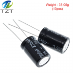
are we talking about something like that which is 1in tall (give or take!):
1658992178749.png

if so, that's on a PCB with all sorts of bits and pieces on it. I've rarely had good results replacing burned/popped/busted capacitors tbh. Usually something more important is foobarred before they pop (experience with a couple of inverters that got wet and a large UPS that was 10+yo)
Post a couple of pics of the whole board where they reside and check carefully back and forth for any telltales of over current burning tracks, blackening other components and busting other smd components.

and finally, when you say blown capacitors is that the top crossed ali cap fully open and contents all over the place or just bulged a bit and out of value?

By all means replace them (cost nothing!), but don't be shocked if it still doesn't work!
May as well start enquiring about a new PCB, but make sure that as julians mentions above that's not related to changes/rewiring done on the overall system. Debugging burning one PCB at the time is an expensive hobby :-(

good luck

V.
 

Portofino

Well-known member
Joined
10 Apr 2011
Messages
12,173
Location
Boat- Western Med
Visit site
I was told by a boat sparky (does emergency call outs for sun seeker Cote d Azur so very busy ) never run the geny + charger and engines ( alternators whirling away ) together .

You can run the geny + engines together of course , but don’t flick the charger( s) switch .

On the same vein the shore power +geny have a 3 way switch . Shore - Off - Geny .It’s either or , just one not any combo of two or all three.There’s a reason !

Without being accused of mega over simplifying .I take it’s as water flowing , water pressure .
The “water “ out of the geny needs to be higher pressure than where its intended to end up .Be it batts ( tanks to store it ) or a Aircon unit , charger etc which use it , drip it away consume it .

If you place something in that pipe age that reverses the flow ie sends “ water “ back , out pressures the genys out flow , then somethings gonna bust in said geny .It might via capacitors ,be able to store a transient amount of juice , but keep exceeding that it blows .Something like that .

So say if run the geny for what ever reason I always give it something to do , enable the “ water “ to run somewhere.

The 3 way switch is a valve with shore mains supply in my mind , the geny supply + pressure and mains pressure never see each other as a result .

How ever having said all this it’s not beyond the witt of man to invent ( and successfully market ) some kinda Carlos Fandango super dooper valve that reckons to prevent my “ back flows “ thus enabling stuff all , being on simultaneously. Connected up together running as one .

From post #1 the thread Julian. ^ Quoted .


AC charging was first. I added a 3000W Xantrex inverter charger and dedicated it to the house bank. I didn't really need the inverter, but this was the only way to get 150A charge current out of the charger.
I then rewired Cristec to the 3 remaining banks.

Alternator was more of an issue. The stock Volvo alternator on the D4 is capable of outputting 115A, but it doesn't do that in the stock configuration. My initial thought was to upgrade the alternator with the likes of Balmar. However this engine is electronic and Balmar could not definitively explain how they will interface with the engine. Not wanting to risk EVC alarms, I moved on. I found an external controller from Nordkyndesign, got it setup, but while the voltage on the atteries went up, the current on shunts showed almost nothing. After tracing the whole negative bus I figured out that the yard upgraded the positive wire from the alternator and ran it to charge separators, but left the thin factory negative wire running to the starter solenoid. I left the factory wire as is and added a 1/0 wire from the alternator to the negative bus bar, which immediately brought up the current values out of the alternator, I reconnected the shunt and tested charge parameters. Everything looked good on house batteries, but thruster and engine batteries were getting overcharged - more rewiring.
I added a victron DC-DC converter hanging off one of the charge separators and wired the output to another charge separator. Since the charger can only handle 30A, the charge parameters looked a lot better.
So the wire from the alternator goes to the charge separator input, output 1 goes to house batteries, output 2 to DC-DC converter. Converter output go to another charge separator that splits output between thruster and engine batteries.
This setup should also handle LiPO4 batteries once I'm ready to swap. The AC chargers are separate, so I can have different charging profiles between AGM and LiPO4 while on shore power and generator. While underway, the alternator controller will charge with a LiPO4 profile that would then be converter to AGM with DC-DC converter. If BMS decides the disconnect the lithium bank, the AGM batteries will still be in the circuit and alternator won't be running without load.”
 
Last edited:

AlexLbk

Member
Joined
4 Jul 2022
Messages
56
Location
New Jersey
Visit site
pics would help, but looks like you're after two small PCB mounted type capacitors that you'd get for pennies from Farnell, RS components, and all sorts of el.components shops!
are we talking about something like that which is 1in tall (give or take!):
View attachment 139587

if so, that's on a PCB with all sorts of bits and pieces on it. I've rarely had good results replacing burned/popped/busted capacitors tbh. Usually something more important is foobarred before they pop (experience with a couple of inverters that got wet and a large UPS that was 10+yo)
Post a couple of pics of the whole board where they reside and check carefully back and forth for any telltales of over current burning tracks, blackening other components and busting other smd components.

and finally, when you say blown capacitors is that the top crossed ali cap fully open and contents all over the place or just bulged a bit and out of value?

By all means replace them (cost nothing!), but don't be shocked if it still doesn't work!
May as well start enquiring about a new PCB, but make sure that as julians mentions above that's not related to changes/rewiring done on the overall system. Debugging burning one PCB at the time is an expensive hobby :-(

good luck

V.
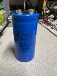
They are certainly not small and are not on the PCB. PCB looks fine visually, there is a board for each inbound phase and they look like proprietary boards so I have no way of testing it. The capacitors are off the board, there are 12 of them connected to bus bars.
So far I found one distributor in Germany that has them. I am attaching an image.IMG_2633.jpg
 
Last edited:

AlexLbk

Member
Joined
4 Jul 2022
Messages
56
Location
New Jersey
Visit site
Alexlbk, You're the same person that recently 'redesigned' his battery charging system aren't you?

Battery charger redesign

Could this issue be related to that redesign?
I considered that question too, but this is how it was designed at the factory, I just made the alternator smarter so it can actually charge based on battery state not just dump 14 volts into them. It’s also hard to imaging that voltage would flow backwards through the batteries into the charger and affect the generator, not the charger. It’s also possible that capacitors are the victim of whatever broke, not the cause. That said I will need to replace them anyhow and the alternative is shipping a 60 lbs inverter across the country for someone to look at, which I might need to do anyway if the issue persists with new capacitors. My issue is finding the capacitors, which are not the Chinese capacitors I get on eBay to repair computer boards, these are large industrial capacitors screwed in with bus bars and torqued to spec. They need to be those specific capacitors or they won’t fit properly. That said I did find one vendor in Germany so we will see what happens.
 

AlexLbk

Member
Joined
4 Jul 2022
Messages
56
Location
New Jersey
Visit site
since they are not the small PCB mounted ones I wrongly assumed, I'm more hopeful that these big boys will get the thing running! fingers crossed.

btw, is it them:
https://gr.mouser.com/ProductDetail/KEMET/ALS30A222KE250?qs=sGAEpiMZZMvwFf0viD3Y3bzn7LR4wbx4b%2Bc4gZ/wA%2BE=
30euro a pop (ignore the pic its lib pic, look at the specs)
IIRC there's a mouser in the US

V.
Thank you, it's very close (tolerances are tighter), but size is different from the other capacitors. It needs to be F&T.
 
Top