Drogue Chain Plates Strength?

thinwater

Well-known member
Joined
12 Dec 2013
Messages
4,291
Location
Deale, MD, USA
sail-delmarva.blogspot.com
I wonder if the Goodall failure does not give us some useful insight regarding the forces involved. It is the only line failure I know of, and it probably happened because the connections were knotted rather than spliced. There is also some question as to whether the tail weight was too light, resulting in some snatch loading. Additionally, you should always expect single-leg loading on a bridle; waves don't come from one direction, and the worst hits often result from this. So it seem Jordan's estimates were remarkably good. Have there been any chain plate ors hackle failures?

And then everything that was said about strength.

Let's not overlook the hull and soft parts:
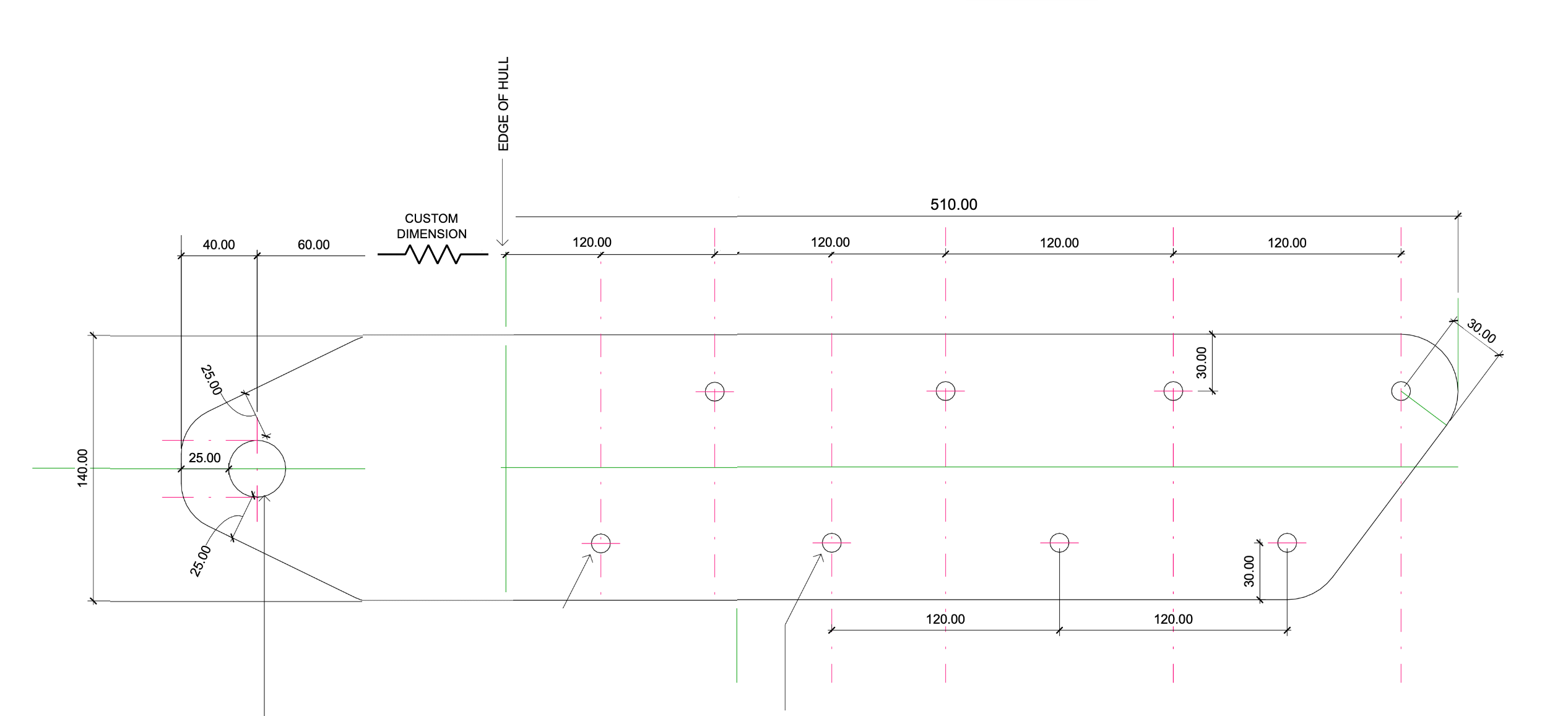
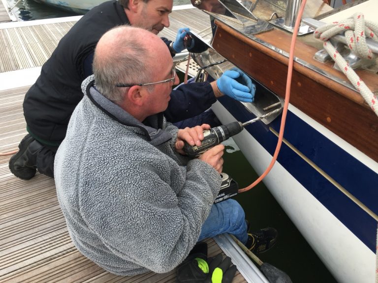
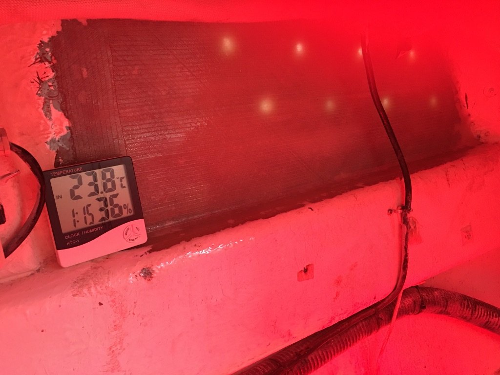
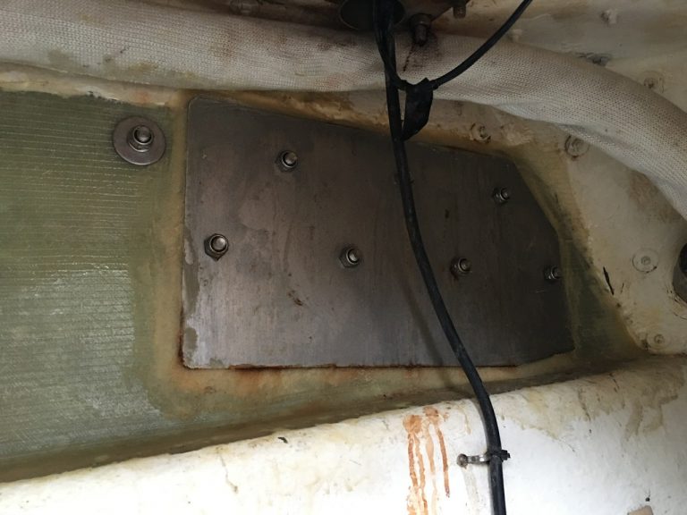
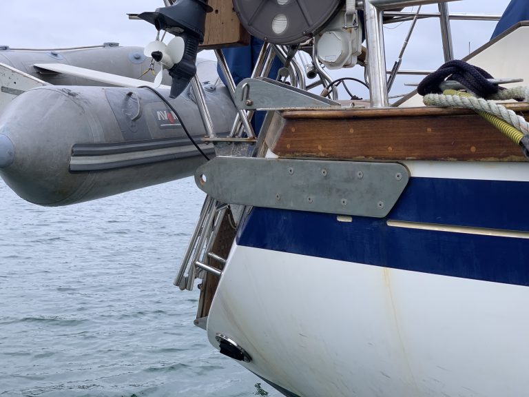
  • Hull. Evaluate the layup if you have the skills. If it is not strong enough, lay glass on the inside, over a large area, until it is. Calcullate all of this with the knowledge that the dirrection of pull will swing vertically at least 45 degrees and latterally between the bridle angle and as far as 60 degrees. I really don't want to pull a hole out of my boat.
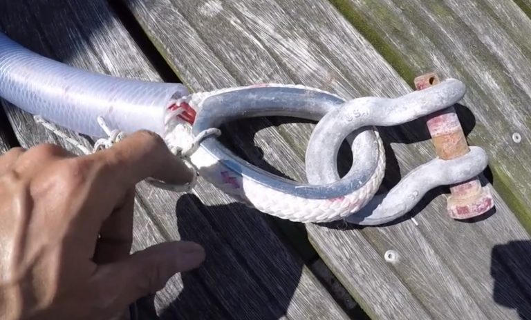
  • Chafe where the bridle eye meets the bridle plate shackle. One bridle nearly cut through in a moderate storm because he used a cable thimble instead of a closed thimble, and the ends are sharp. Under high load thimbles become loose because the rope stretches. You only see this if you do testing to high load percentages. In nylon, the eye will stretch 20% longer and the thimble will be very loose. Is there ACTUALLY any movement between the rope and the shackle, or does the shackle absorb all of the rotation? For example, we use soft shackles to connect snubbers and they do not chafe. Would we be better off using an oversized Dyneema briddle, larkshead to the shackles, and no thimble? You could cover it with webbing for some chafe protection if you like. You will not need the thimble for bend radius.
  • Interlocking eyes down the line. I am not aware of any failures or chafe. But some people think they should use shackles.
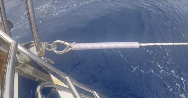
  • Too long bridle arms. If more than ~ 2-3x the beam you will get slack, after which they will snatch tight. Snatch loads dramatically reduce the fatigue life of most fibers. Longer bridles are not always better.
 

Laminar Flow

Well-known member
Joined
14 Jan 2020
Messages
1,849
Location
West Coast
Visit site
For the holds defined for the strapping, 12,656lbs and 20,246lbs - at what angle are these loads applied?

The question is not what tension can this strapping accept but at what point will it yield if loaded at an angle, and some comment needs to be included at what angle the tension might be applied.

Jonathan
That is a correct and important observation. The strapping, as any chainplate , should be aligned with the direction of the force.

Personally, I would install a couple of decent size cleats or strong posts to the deck and with a set of stout fairleads as closely aligned with the direction of force as possible.

I have spent time at sea running off trailing a drogue during a storm. I have to say I would not consider investing in a dedicated point of attachment for something that one, in all likelihood, may never have to use. On the other hand, it makes every sense to invest in excellent and super strong cleats and fairleads that can be used for towing or mooring in adverse conditions.

Edit: Having done this kind of thing, I wonder about the wisdom of tethering your boat to the tune of a 9 t force while going downhill in a storm. The forces on that poor rudder must be phenomenal and in my own experience a drogue can encourage the following seas to walk over the boat.
 
Last edited:

thinwater

Well-known member
Joined
12 Dec 2013
Messages
4,291
Location
Deale, MD, USA
sail-delmarva.blogspot.com
That is a correct and important observation. The strapping, as any chainplate , should be aligned with the direction of the force.

Personally, I would install a couple of decent size cleats or strong posts to the deck and with a set of stout fairleads as closely aligned with the direction of force as possible.

I have spent time at sea running off trailing a drogue during a storm. I have to say I would not consider investing in a dedicated point of attachment for something that one, in all likelihood, may never have to use. On the other hand, it makes every sense to invest in excellent and super strong cleats and fairleads that can be used for towing or mooring in adverse conditions.

He makes good points. Jordan said this:

" There are three areas that require special attention:

1. The attachment fittings for the bridle of the drogue towline at the corners of the transom must be capable of carrying 70% of the towline design load. For a 7500 lb. displacement boat each fitting must be capable of carrying 5300 lbs. Many yachts are equipped with a genoa track which runs aft
to the transom. Such a structure, which distributes load along the hull, could be provided with a special eye at the transom for
attaching the bridle.

If the nylon towline is led through a chock instead of attaching directly to an eye, experience suggests that chafing may occur even with good chafing gear installed. Consideration should be given to the use of a short length of wire cable running through a stainless steel chock before attaching to the nylon line."

Also this:


"Attachments on the Hull
The hull attachments for the drogue should be as far outboard and as far aft as possible. I have no information on the ultimate strength of a typical sheet winch installation, and it would be difficult to evaluate each structure. Unfortunately, a winch is not an ideal structure, since the load is applied above the deck line and tends to overturn the winch and pull it out. The optimum attachment for the drogue is clearly a strap similar to a chainplate, bolted to the hull at the corners of the transom and extending aft with a shackle.

For a load of 14,000 lbs, a strap ¼ x 2.25 x 18 inches attached with six 3/8 bolts would provide a conservative design.

A large steel cleat would be acceptable if the deck is thick solid fiberglass and a steel plate is provided underneath."


So yes, a cleat is acceptable, but the location and type of fairlead is critical. What he did not say, was that ropes at very high load can chafe and heat inside the chafe gear. I've actually welded rope to the webbing when drop testing using nylon rope. For this reason, the bridle could be polyester (less stretch = less movement). The bridle almost certainly should not be nylon.

Note that he used 3/8" bolts in the chain plate. A single 3/8-inch SS bolt is rated at about 4900# in shear, or about 35% of the total load. He did NOT assume the bolts would share the load evenly, because unlike a rigging chain plate, the load will be off-axis. It will also probably be angled downwards 10-20 degrees, something you never see (people always install chain plates level, though high load is nearly always when you are getting pulled up a steep wave). It may also be angled inwards, as much as 90 degrees across the transom, though 30-45 degrees is more probable (not outwards--the other bridle leg is holding that... unless it goes, in which case the load will always be at an outward angle, entirely on the last bolt).

Cleat strengths are never posted by manufacturers. I don't understand that. I've only seen one published test series, and it suggested it is usually the fasteners that go first, but not always.

A standard chock is probably a bad choice. Many are atrociously designed, with sharp edges and a way for the rope to jump out. A ships mooring chock, like a low friction ring, would be wonderful. But does any one sell a yacht-sized version? Seems they would be handy for huricane mooring and anchor bridles too. If anyone knows of a source, PLEASE post it.
1613673442250.jpeg

He said he felt the chain plate approach was more error proof.

Interesting topic.
 

Laminar Flow

Well-known member
Joined
14 Jan 2020
Messages
1,849
Location
West Coast
Visit site
Note that he used 3/8" bolts in the chain plate. A single 3/8-inch SS bolt is rated at about 4900# in shear, or about 35% of the total load. He did NOT assume the bolts would share the load evenly, because unlike a rigging chain plate, the load will be off-axis. It will also probably be angled downwards 10-20 degrees, something you never see (people always install chain plates level, though high load is nearly always when you are getting pulled up a steep wave). It may also be angled inwards, as much as 90 degrees across the transom, though 30-45 degrees is more probable (not outwards--the other bridle leg is holding that... unless it goes, in which case the load will always be at an outward angle, entirely on the last bolt).
The difference between bolts and machine screws is that bolts have, unlike machine screws, an un-threaded section. If it is this part that is loadbearing, then indeed, a 3/8th bolt will support 4900# in shear. The OP's pic however shows machine screws.

The best solution would be to have a couple of deadeyes welded to some rectangular bases and to bolt the assemblies through the transom at the upper outboard corners with substantial backing plates to spread the load.
Now all the bolts would be loaded in tension, or nearly so, or most of the time at least, and it would be more capable of handling misaligned forces.
 

Neeves

Well-known member
Joined
20 Nov 2011
Messages
12,209
Location
Sydney, Australia.
Visit site
The chain plates should be angled such that, in theory, they are only in tension - in the straight line determined by the bridle dimensions. However the reality is that the tension will sometime be all on one arm of the bridle and at unpredictable angles. The angles will be constantly changing and I can visualise that if it does yield - it will do so repetitively during the course of usage. It is for this reason I would be having a focus on the yield strength under those conditions. If it meant taking a piece of the strapping and mocking it up to test it - that is what I would do, bugger the theory - do it! Buying an extra piece of 316 strapping is peanuts, mocking it up - really not difficult - borrow or rent a load cell.

I did exactly this to find the strength of an anchor shank at the time of the bendy shank saga.

What is surprising is that the question arises at all. It seems pretty fundamental that the method of attaching the JSD to a yacht is critical , the options should have been defined by someone and the design of options quantified. Possibly one issue is that JSDs and Para anchors are not sufficiently mainstream. It is also a larger topic and obviously there is not even real agreement that chain plates are the optimum - Sadly its not a sexy topic like anchors where you will engender much support for the work.

I also find it surprising that Jordan has not quantified the issues, it all seems that little bit subjective, and that people who have commented and researched JSDs have not attempted to do the work, or ensure the work is done. JSDs were introduced decades ago and we are still talking about design. Beggars belief.

I suspect that the lifting industry, and rock climbing (for whom I am developing a lot of respect - and who show some in the marine industry as a bunch of dangerous amateurs, who cannot even check developments in lifting and climbing) already have devices that would perfectly answer many of the issues (possibly with minor modifications). They design a whole host of 'interesting' and imaginative designs for a myriad of applications and I am sure there are some that would suit. They are all cast and would need to be galvanised (and possibly modified slightly). They discarded many of the devices we use decades ago and replaced them with better components, hooks come to mind, but shackles, chain etc.


And I do wish there was only one thread on a topic at a time :(

Jonathan
 

geem

Well-known member
Joined
27 Apr 2006
Messages
7,408
Location
Caribbean
Visit site
We carry a JSD but have never used it in anger. We don't have dedicated plates fixed to the hull. I thought long and hard about this. It would be difficult to locate such plates on our hull due to the tongue and groove teak panelling in the aft cabin. In addition, this part of the hull is not as strong as our deck. The hull to deck joint on our boat is substantial. The hull moulding is glassed to the deck moulding then the joint is through bolted every 75mm with an M8 bolts through a substantial aluminium toerail. The aft cleats are located adjacent to the toerail in the thickened section of solid deck. The cleats are aluminium, 400mm long, and bolted through the deck with four M10 bolts. We connect the bridle to 1m lengths of 1” dyneema strops that have spliced loop ends. These strops pass through the toerail fairleads then on to the cleats. The dyneema strops have leather chafe protection at the cleats and fairlead locations. The cleats then have a second back up strop to large shackles bolted through the toerail holes. We hope we never need to use the JSD
 

zoidberg

Well-known member
Joined
12 Nov 2016
Messages
5,831
Visit site
I wonder if the Goodall failure does not give us some useful insight regarding the forces involved. It is the only line failure I know of, and it probably happened because the connections were knotted rather than spliced.

There were numerous comments in here - and in many other places - about the likely cause of failure of the drogue-line on Goodall's boat. I made some of them, and I actually asked S. Goodall. at a presentation in SIBS. She has been reticent with answers, perhaps due to a sense of loyalty to the manufacturer of the JSD she carried AND to Marlow Ropes, a principal sponsor.

It is probable that the 'new' rated strength of the line, chosen using Don Jordan's simplistic diagram from 1980, was insufficent to the task because the LADEN weight of the boat was far in excess of the builder's 'light-ship' data.

It is certain that there were several unnecessary knots in the assembly. Photos of the actual JSD rig taken prior to departure - and posted on here - show long spliced loops between joined sections, and those long loops also with a superfluous double figure-of-eight knot tied in. Each one of those knots weakens a rope's ultimate strength - as professional research for the European climbing industry showed decades ago - and so also does joining two or more sections of a JSD using a 'larksfoot' or similar. One wouldn't climb on a rope with that kind of join. One wouldn't lift a cage of miners up a shaft with a lifting-cable joined like that.

There is NO justification for using several discrete lengths of JSD joined together with knots like that.

There is NO justification for the strength of the individual arms of a bridle being less than that of the main rode.

Don Jordan as a practical engineer did us a great service by indentifying a lethal problem and researching - with his own funds - a solution. He did not seek to market/sell his solution. Having researched and proved the principle, he gave it to us to use, to take forward and improve.

I can well understand him using thick nylon rope , in 1980, for that's what he had. But nylon rope is far from being the best material in this role. 'Thinwater', in his day job, and 'Neeves' ( both engineers ), I and others know why.... and the several reasons have been posted here and elsewhere. One is that nylon weakens substantially when wet.

We have far stronger, lighter, and more robust ropes available to us today and we have large international rope-making businesses with the facilities for the testing that's warranted. The knowledge is almost certainly available within the associated 'lifting' industry. There are even International Standards that can be considered.
 

thinwater

Well-known member
Joined
12 Dec 2013
Messages
4,291
Location
Deale, MD, USA
sail-delmarva.blogspot.com
The difference between bolts and machine screws is that bolts have, unlike machine screws, an un-threaded section. If it is this part that is loadbearing, then indeed, a 3/8th bolt will support 4900# in shear. The OP's pic however shows machine screws.

The best solution would be to have a couple of deadeyes welded to some rectangular bases and to bolt the assemblies through the transom at the upper outboard corners with substantial backing plates to spread the load.
Now all the bolts would be loaded in tension, or nearly so, or most of the time at least, and it would be more capable of handling misaligned forces.

"He" reffered to the quote from Don Jordan, within my same post, not the thread.
 

thinwater

Well-known member
Joined
12 Dec 2013
Messages
4,291
Location
Deale, MD, USA
sail-delmarva.blogspot.com
... The best solution would be to have a couple of deadeyes welded to some rectangular bases and to bolt the assemblies through the transom at the upper outboard corners with substantial backing plates to spread the load.
Now all the bolts would be loaded in tension, or nearly so, or most of the time at least, and it would be more capable of handling misaligned forces.

Interesting idea, except...

  • Now the laminate is loaded outwards instead of in shear. On most boats I fear you would just pull a hole, if not pull the whole transom out, backing plate and all.
  • The bridle base is narrowed, which means more yawing.
The chain plate method is simple and well proven, it's just a matter of adding factors to cover all of these issues. My initial point is that Don Jordan did just that; his plates are stronger than the load he described, to allow for off axis loads and so forth. And he implied, I believe, that his design was only a starting point. He used 17 KSI as a design tensile stress.
 

Tim Good

Well-known member
Joined
26 Feb 2010
Messages
2,798
Location
Bristol
Visit site
Lots of good info on this thread but based on the feedback I got in 2016 this is my setup now:


46E5E8DF-44F3-4071-8C86-335D3A87230B_1_105_c-768x576.jpeg


588C370F-AE6B-450A-AF4B-14D1FE533189_1_105_c.jpeg


CF1E0388-05CD-42AB-9469-46ED9277A69D-768x576.jpeg

Above: We reinforced the hull from the inside with additional epoxy and matting prior to fitting a large stainless backing place. That said the layup of our hull is Lloyds certified and the thicknedd here was around 20mm solid GRP anyway before we added the plate and extra GRP.

Drogue-Chainplates-768x576.jpg

Above: Here are our 8 bolt chainplates attached. Note the overhang is quite large due to our davits and Hydrovane. If you can, less overhand is better I think.

JSD-Bridle-Chaffe-Protection-768x401.jpg

Above: Note the large plastic pipe I have over the first part of the bridle to eliminate any chance of chafe should the boat veer off to one side significantly. In my experience this didn’t happen but its good to know the protection is there.

18D26BD4-14C1-4978-B284-F5BFF0A12D31-768x464.jpeg

Above: I specifically wanted Hard Eyes on the bridles as I felt standard open versions were a chafe risk. Note also the Crosby G2140 Shackles with a SWL of 7T and a breaking strength of around 25T. That is more than sufficient according to Don Jordan’s specifications which say each bridle should be capable of taking 50% of the boats displacement. Our boat is 17T.

GPTempDownload-3-768x576.jpg

Here is the Drogue stowed in position ready to be used. It is lashed forward of the steering pedestal and then the bridles are already attached and zip ties keep them out of the way. It took me only a couple of minutes to move it around aft of the wheel and in place where I could throw the chain overboard and let it deploy automatically.

 
Last edited:

Neeves

Well-known member
Joined
20 Nov 2011
Messages
12,209
Location
Sydney, Australia.
Visit site
Northcave - there is nothing wrong with those shackles - but they are the same strength as the G209a shackles. The difference is your shackles are arguably more secure as they incorporate a locking nut and cotter pin. The G209a shackles simple rely on the thread of the cotter pin and that the cotter pin cannot work itself out. If you use Loctite and mouse the pin I think the G209a will be as safe. Van Beests Green Pin shackles can be sourced, at the size you were using to the same quality and might be easier to find. Peerless, Campbell, Columbus Mackinnon, Yoke also make shackles to the same specification as the G2140 shackles and to the Crosby G209a specification. Many of these shackles are only available in larger sizes - and my common focus is for smaller shackles 3/8th" of the 209a design for use on an anchor shank - and then you are really restricted to Crosby. Noting that size is a determinant from whom you source and most of these shackles are used in lifting and are of American origin, except Yoke (Taiwan) of the ones I have tested 3/8th" size - Campbells are the best.

If you know people in America well enough that they could source the shackles for you - it solves all the problems. But sending a few shackles to a private buyer in the UK (or Australia) is simply not worth the effort for most of these manufacturers and they have a large enough home market without the need to service distributors in Europe.

You can source heat shrink covers for ropes, they are used in climbing ropes, but I don't know how the heat (to shrink the cover) impacts rope strength. The facf that they are used in climbing ropes suggest the impact of the heat is acceptable. I use these heat shrink covers when I make eyes in climbing rope and the climbing ropes I have bought have had sewn eyes with these heat shrink covers - the sewing and the covers being installed by the rope manufacturers.

I do note your chain plates have a large overhang but that your chain plates are very wide. Personally I would have had an oval hole, to allow the shackle eye to pass through the plate. There is little room for the articulation of the shackle pin in your installation.

I also note your large overhang of the chain plate - but also note the reason why.

Jonathan
 

Neeves

Well-known member
Joined
20 Nov 2011
Messages
12,209
Location
Sydney, Australia.
Visit site
Zoidberg,

Your comment on the use of 20th Century materials, or their absence of use, in this particular application is valid and it extends to other applications as well. There have been a number of developments in rope technology, Kevlar and Dyneema being but 2 and there are other materials Duplex stainless and high tensile steels being others. Kermantle rope is now de rigour in climbing - it can be made in larger sizes than 12mm (I had some made in 14mm - that's how I know) but extending its use beyond climbing - its like shouting on the moon.

On the problem of the weakening of nylon when wet - it would be possible to design a rope with a nylon core and a dyneema outer cover. It might be possible that the cover could be engineered that were the core to weaken or stretch too far then the cover would provide a restriction to further degradation (and failure). But who is going to invest in any development work?, how big is the market? - is it worth the effort for Marlow for a few JSDs?, would anyone here be the first to use it......?

I know - the cover would need to be 'loose' to offer opportunity for the nylon to stretch, so the cover needs to be 'stopped' as well as being loose. It does not appear to be beyond possibility.

The problem with drogue's is they are very niche and they, drogues, have merited little attention, and even with a regularly quoted failure, SG's, still have not merited much attention. Jordan may have hoped that his design would be honed and better quantified - it has not happened, failures are occurring and in some respects we are no further forward than when he released his design (I recall it being discussed, for home build, in PBO). I say drogues have not merited attention - there has been much forum comment - but the big questions still remain unanswered - and the use of newer materials has not enjoyed much attention.


I don't have the answers, like Jordan - the work he did he did for free, an investigation on use of new materials would merit one article in PBO - that will not pay for the work.


Jonathan
 
Last edited:

Tim Good

Well-known member
Joined
26 Feb 2010
Messages
2,798
Location
Bristol
Visit site
I would have had an oval hole, to allow the shackle eye to pass through the plate. There is little room for the articulation of the shackle pin in your installation.

Jonathan

Yes that was the intend and I asked for an oval hole but it came round. I had intended to have it changed at some point but only if it can be done without removing. Maybe one day.
 

Neeves

Well-known member
Joined
20 Nov 2011
Messages
12,209
Location
Sydney, Australia.
Visit site
Yes that was the intend and I asked for an oval hole but it came round. I had intended to have it changed at some point but only if it can be done without removing. Maybe one day.

For me oval holes are more difficult. I have to drill 2 round holes and then hand file the bit in between - certainly best done on a work bench. If you were making them - dead easy, laser or water cutting. In situ - really hard work.


I made some bridle plates in 7075 aluminium and had them hard anodised. The hard anodising was black, because that's what they were doing for Ronstan LFRs (a different colour was more expensive). I then upped my game and had them made in Duplex stainless, which is now my recommendation. I provided the aluminium versions as an example and a full drawing - when delivered they were perfect - except in stead of bare metal, or polished (which is what I expected) they arrived - painted black. It never occurred to me stainless would be painted.

Jonathan
 

zoidberg

Well-known member
Joined
12 Nov 2016
Messages
5,831
Visit site
except in stead of bare metal, or polished (which is what I expected) they arrived - painted black. It never occurred to me stainless would be painted.

What paint and primer regime was used, pse? I have some stainless I want to paint black....
 
D

Deleted member 36384

Guest
Rather than oval holes orientate the plate such that the shackle pin hole is vertical in the plate and allows it to articulate in line with the bridle and bear the load over the full CSA of the pin. Of course this would require the plate to be thicker at the end and tapered to avoid a big lump on each quarter, but hardly a difficult thing to have machined. On my own boat with the canoe curve and the gunwale cap, quite a thick plate could be incorporated without sticking out.
 

Neeves

Well-known member
Joined
20 Nov 2011
Messages
12,209
Location
Sydney, Australia.
Visit site
Rather than oval holes orientate the plate such that the shackle pin hole is vertical in the plate and allows it to articulate in line with the bridle and bear the load over the full CSA of the pin. Of course this would require the plate to be thicker at the end and tapered to avoid a big lump on each quarter, but hardly a difficult thing to have machined. On my own boat with the canoe curve and the gunwale cap, quite a thick plate could be incorporated without sticking out.

A drogue will impose tension in both the vertical and horizontal (as the yacht and the drogue will be in different parts of a swell).

Having the bow of a shackle though the hole in the chain plate allows maximum articulation.

There are alternatives and G60 Cromox hammerlocks (I think Ketten Waelder call them connecting links) come to mind but they only offer WLL of upto around 6t (from memory). Gunnebo, now owned by Crosby, might supply galvanised hammerlocks to the aquaculture industry (and they have just released a G80 galvanised chain for Aquaculture).

Or something like this

CWI Connex connecting link

These are not cheap and an alternative would be the same device in alloy steel and painted and simply discard (and replace with new) when you decide they are unsightly. In alloy steel they come in at least G100 grade. Or you talk to your friendly galvaniser and have them coated (but only consider coating a G100 version, that's what I use when I have them galvanised.

Jonathan
 
Last edited:

Kukri

Well-known member
Joined
23 Jul 2008
Messages
15,568
Location
East coast UK. Mostly. Sometimes the Philippines
Visit site
I’m coming to this thread late, but it seems to me that the load on the rudder is going to be less using a series drogue than anything else. My own limited experience suggests that when heaving to one must fore reach slowly to keep the boat from sitting back on her rudder and the limit of heaving to is reached when she won’t do that.
 

rogerthebodger

Well-known member
Joined
3 Nov 2001
Messages
12,459
Visit site
I'm also ate to the thread.

If you wish to make the existing hole oval in place I would use a burr in a die grinder

I would also have bent the outer projection to closer to the angle of the bridle or fit the chain plate on the flat on the deck with an angled support plate inside bolting through the deck and side of the boat giving a better load pull.

I would also fit a rigging toggle as we do with rigging to allow the pull to not introduce any bending in the chain plate.

I have twin back stays so I would attach to wise toggle to the rigging pin of my backstay chain plated as this is one of the strongest point on the aft of my boat
 
Top