Building the Ultrasonic Antifouling Kit from Jaycar

Joined
20 Jun 2007
Messages
16,234
Location
Live in Kent, boat in Canary Islands
www.bavariayacht.info
The cable supplied by Jaycar has been left uncut...

The cable is much longer than I expected, which bodes well for the dual unit I'm considering designing.

I'd be interested in knowing the cable length, and the size of the conductors. Do you have a micrometer or vernier/digital caliper? The diameter of a single strand, and their number would be very useful.

Also, are there any markings on the transducers - probably to late for Norman to answer!
 
Joined
20 Jun 2007
Messages
16,234
Location
Live in Kent, boat in Canary Islands
www.bavariayacht.info
still do play with electronics as i'm a freelance sound engineer and also like modifiying things (like mod a scanner to make it an ais receiver)....

@bitman: this is also a project I'm considering. Could you PM me if you have any info, or perhaps a new thread (with a PM "heads-up" if you could)?

ready to start building
@bitman: I like your "helping hands" unit, where did you get it?

PS Say "Hi" to Tux for me :)
 
Last edited:

bitman

New member
Joined
1 Apr 2009
Messages
349
Location
West Sussex, UK
www.bit4net.com
transducer AU5556

The cable is much longer than I expected, which bodes well for the dual unit I'm considering designing.

I'd be interested in knowing the cable length, and the size of the conductors. Do you have a micrometer or vernier/digital caliper? The diameter of a single strand, and their number would be very useful.

Also, are there any markings on the transducers - probably to late for Norman to answer!

transducer u/sonic 50w 40khz
P1010584.jpg
 

bitman

New member
Joined
1 Apr 2009
Messages
349
Location
West Sussex, UK
www.bit4net.com

Norman_E

Well-known member
Joined
15 Mar 2005
Messages
24,696
Location
East Sussex.
Visit site
Switch Box

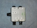
I have bought a waterproof junction box and fitted the two switches provided by Jaycar and three cable glands into it as shown in the photo. This will be mounted out of sight below the chart table, with 12 volt supply coming from the bilge pump circuit breaker, which is always in the on position when the boat is in water, and which has 15 amp capacity, and is capable of running both units and the bilge pump.

tn_Photo 13.jpg
 
Last edited:

Fr J Hackett

Well-known member
Joined
26 Dec 2001
Messages
66,166
Location
Saou
Visit site
Just got the letter from Parcelfarce asking for £35 so it looks like I have not had to pay any additional postage from Australia. Ordered on the 4th Jan here today, not bad. Should be able to start building this weekend.
 

Norman_E

Well-known member
Joined
15 Mar 2005
Messages
24,696
Location
East Sussex.
Visit site
Just got the letter from Parcelfarce asking for £35 so it looks like I have not had to pay any additional postage from Australia. Ordered on the 4th Jan here today, not bad. Should be able to start building this weekend.

You jammy begger!

Its an easy enough build, once you have correctly identified the resistors.
 

Fr J Hackett

Well-known member
Joined
26 Dec 2001
Messages
66,166
Location
Saou
Visit site
A question for Norman, I have just opened my packages and notice that the transducer has a recess in the face, did you make any provision when potting the transducer to ensure that this was filled or did you just assume that it would remain unfilled when you poured in the potting compound.
 

Norman_E

Well-known member
Joined
15 Mar 2005
Messages
24,696
Location
East Sussex.
Visit site
I have no idea whether filling the recess is necessary or not but this is what I did.

I filled the recess by clamping the socket into the fixture that I had made, and adding a few millimeters depth of potting compound then filling the recess, before inverting the transducer into the socket and pressing it down. After that, I pulled the cable back though the gland to remove excess length, but not pulled tight, before tightening the gland. You have lots of time to work so the next step is to ensure that the compound is well up the sides of the transducer, but not over the top. Press the transducer firmly down so that the 1mm plastic spacers are pressed in contact with the foil (or cling film if you used that) and tilt it to one side and hold it for a few minutes so that any air bubbles below the transducer find their way to the surface. Put it back level and top it up. Whilst doing that I used a small thin screwdriver pressed down into the socket of the Allen screw to stop any tendency for the transducer to move or float up as the compound was put in, and carefully withdrew the screwdriver once pouring was complete

As an aside the instructions show a picture of five little bits of plastic used as spacers. You only need three spaced equally to make it sit level. Same principle as a milking stool.
 

Fr J Hackett

Well-known member
Joined
26 Dec 2001
Messages
66,166
Location
Saou
Visit site
Many thanks for that allways good to have someone from the pioneer company out in front:) The whole kit looks very good and worth the money. Hopefully I should be able to do the installation in the next 4 weeks and report with some photographs although that will be small beer in comparison with your efforts.
 

Plamen

New member
Joined
4 Jan 2011
Messages
44
Location
Germany / Greece
Visit site
How to monitor operation?

What I am missing on the Kit, is a way to display/monitor the operation by a simple way. I don't mean the presence of input voltage, but the function of all curcuitry up to the input of the transformer. Ideally, this could be a LED which will flicker, or a simple beeper, or something else.
I have friends, they can desing such things, as simple as I use the keyboard to type this message down.
Will post you with results, hopefully soon.

I was asured by Jaycar, my 2 kits are on the way, and another 4 will follow soon. I will not start assembly, before I have a solution of my question.

BTW, what could be the life expectance of the transducer element itself?
Also, are any issues to be expected with the life expectance of the epoxy glue, exposed to permanent vibration?
 
Last edited:

Norman_E

Well-known member
Joined
15 Mar 2005
Messages
24,696
Location
East Sussex.
Visit site
I wonder if somebody who has got it's kit ready, could measure and post here the actual Amp consumption @ 12VDC.

I connected a multi meter, and could not get a reading on the amps scale. It is no use trying to read resistance without a battery connected as resistance simply drops slowly away once you connect the meter. The article states that continuous power drain is three watts or less.
 

Plamen

New member
Joined
4 Jan 2011
Messages
44
Location
Germany / Greece
Visit site
3 Watts?? Enough to kill algae?

I connected a multi meter, and could not get a reading on the amps scale. It is no use trying to read resistance without a battery connected as resistance simply drops slowly away once you connect the meter. The article states that continuous power drain is three watts or less.

With 3 Watts expected power drain, you should be able to measure 0.25 Amp, correct? 0.25 Amp is good for battery life, but should 3 Watts be enough to kill algae, with all the losses from penetrating the hull? Other manufacturer claim to produce around 15 Watts, with pick current draw of up to 3 Amp. Which is not good for battery life on the other hand, unless you install a solar panel.
 
Last edited:

Plamen

New member
Joined
4 Jan 2011
Messages
44
Location
Germany / Greece
Visit site
I wonder if somebody who has got it's kit ready, could measure and post here the actual Amp consumption @ 12VDC.

here, I find in on the Cilicon Chip brochure :
"While a high-power transducer is used and we do drive it with very high voltages, the actual
power used is not very great so that the typical current consumption from a 12V battery is around 220mA (3A peak)."


It wouldn't be a bad idea, after assembly, to check it's within tolerance.
 

Plamen

New member
Joined
4 Jan 2011
Messages
44
Location
Germany / Greece
Visit site
With 3 Watts expected power drain, you should be able to measure 0.25 Amp, correct? 0.25 Amp is good for battery life, but should 3 Watts be enough to kill algae, with all the losses from penetrating the hull? Other manufacturer claim to produce around 15 Watts, with pick current draw of up to 3 Amp. Which is not good for battery life on the other hand, unless you install a solar panel.

Also from the Silicon Chip Q & A section :

"The continuous power drain of the ultrasonic driver is about 3W or less, depending on the actual supply although the peak powers are much higher, at around 40W or more. To provide this level of power on a continuous basis you will need a solar panel installation of at least 20W. Many boats on swing moorings would already have such a solar panel but it would need to be
augmented by at least another 20W to be sure that the battery is fully charged during periods of bad weather or in winter when there are less hours of sunlight."


Sorry, I should have read it first, before doing wrong conclusions
 

Interlude

Member
Joined
10 Oct 2007
Messages
85
Location
Sydney
Visit site
Ultrasonic antifouler current and operation

I am seeing about 0.3 amps average (measured by NASA battery condition meter, so could well be 0.25 amps) and have had to add another solar panel to keep the house battery up. In terms of checking operation, if you hold an AM transistor radio within a few metres of the unit you will hear it (or at least the interference it generates as it interacts with the received AM station).

I'll let you know in a few months whether I think it is actually keeping the barnacles down.
 
Top