Kelpie
Well-Known Member
After more than two years of excellent service from my DIY 271Ah LiFePO4 pack, I've decided to upgrade and build a second pack.
This time round the cells are slightly different, 280Ah with M8 studs instead of M6 threads.
I specified the same BMS- JBD 200A- but again it's slightly different, with reduced depth of heatsink fins and paired M5 threaded connections, instead of the single larger connections of the previous one.
Building the pack second time round is definitely faster and easier. To start with, I put the pack together along with an old spare BMS, and set it up with a 30A charger. Got a fair few Ah in before one of the cells hit 3.55v, at which point I stopped and put the cells in parallel, then resumed charging using a variable power supply set to 3.6v. I left it like that for a few hours, then reverted to 12v configuration and the bigger charger. This time everything was much better balanced and I was able to take all four cells up to 3.5v together.
Finally I put the cells back in parallel and carefully brought them up to 3.6v with the power supply.
Some people say you should balance at 3.65v but frankly I was running out of power and was keen to call it a day. Hopefully they'll be happy at that. I'm doing all of this using the inverter running off the previously built battery, and a good chunk of today's solar has gone in to the new battery instead of my actual house bank. There are some downsides to life at anchor without a generator.
Next step is to make up the end plates and threaded rod to physically hold the cells together. You don't want any movement between them damaging the studs. I'll mount the BMS on one of the end plates. Then a few cables to make up (easy with a £30 hydraulic crimping tool) and install.
A question for those in the know- the new BMS is designed to take two cables in each side. I think my options are to:
- run a pair of smaller cables, forming a Y, in to a single terminal at one end.
- run a pair of cables and stack the terminals
- ignore one of the connections and just use a single thick cable
I'm thinking the first option is likely the best, but I'm not all that happy about running small cables in parallel. However the individual cables would still be treated higher than the main fuse, so I guess it's ok?
And talking about fuses... I'm thinking of joining the two batteries at the fuse connector, using it as a bus bar. Is there any reason to also have individual fuses on each battery?
Final question. Presently, the MPPTs connect straight to the battery (on the positive side). If I leave that as-is, will I end up with one battery charging preferentially? It seems unlikely given that they're connected by heavy cable.

The cells upon arrival
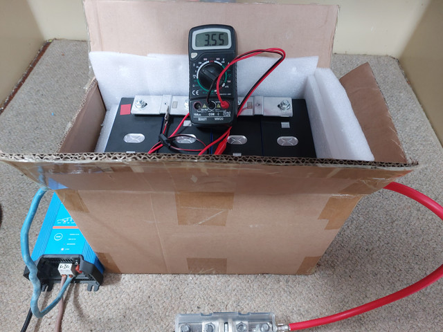
Charging as a 12v pack

Final top balance in parallel
This time round the cells are slightly different, 280Ah with M8 studs instead of M6 threads.
I specified the same BMS- JBD 200A- but again it's slightly different, with reduced depth of heatsink fins and paired M5 threaded connections, instead of the single larger connections of the previous one.
Building the pack second time round is definitely faster and easier. To start with, I put the pack together along with an old spare BMS, and set it up with a 30A charger. Got a fair few Ah in before one of the cells hit 3.55v, at which point I stopped and put the cells in parallel, then resumed charging using a variable power supply set to 3.6v. I left it like that for a few hours, then reverted to 12v configuration and the bigger charger. This time everything was much better balanced and I was able to take all four cells up to 3.5v together.
Finally I put the cells back in parallel and carefully brought them up to 3.6v with the power supply.
Some people say you should balance at 3.65v but frankly I was running out of power and was keen to call it a day. Hopefully they'll be happy at that. I'm doing all of this using the inverter running off the previously built battery, and a good chunk of today's solar has gone in to the new battery instead of my actual house bank. There are some downsides to life at anchor without a generator.
Next step is to make up the end plates and threaded rod to physically hold the cells together. You don't want any movement between them damaging the studs. I'll mount the BMS on one of the end plates. Then a few cables to make up (easy with a £30 hydraulic crimping tool) and install.
A question for those in the know- the new BMS is designed to take two cables in each side. I think my options are to:
- run a pair of smaller cables, forming a Y, in to a single terminal at one end.
- run a pair of cables and stack the terminals
- ignore one of the connections and just use a single thick cable
I'm thinking the first option is likely the best, but I'm not all that happy about running small cables in parallel. However the individual cables would still be treated higher than the main fuse, so I guess it's ok?
And talking about fuses... I'm thinking of joining the two batteries at the fuse connector, using it as a bus bar. Is there any reason to also have individual fuses on each battery?
Final question. Presently, the MPPTs connect straight to the battery (on the positive side). If I leave that as-is, will I end up with one battery charging preferentially? It seems unlikely given that they're connected by heavy cable.
The cells upon arrival
Charging as a 12v pack
Final top balance in parallel