Battery condition

wonkywinch

Well-known member
Joined
30 Jul 2018
Messages
2,029
Location
Hamble, UK
Visit site
I am fairly sure that the manual for my B&G plotter advises exactly that.
Of course in practise that rarely happens on a sailing vessel at the end of the day as the engine is invariably started with all the electronics running as you drop sails, enter your harbour etc

My boat has separate engine start, thruster and "domestic" batteries which are normally isolated from each other. If the engine start is from the same supply as the equipment then there is a risk the battery will drain and be insufficient to start the engine so this situation should ideally be engineered against by use of an isolating switch.
 
Last edited:

B27

Well-known member
Joined
26 Jul 2023
Messages
2,068
Visit site
Back last century, I sailed on a few boats doing RORC and JOG races, it was common to have a small sealed LA battery to operate the VHF. May even have been a rule for offshore? Some boats used that to avoid the GPS cutting out on engine start, because back then, it could take the GPS a long time to boot up again and find a fix, right when you actually want it.

It's pretty common for starting a diesel engine to drag the volts down a long way.
If there's a VSR closed between house and engine battery (maybe due to solar charging?), the engine may drag down both batteries as VSR's generally don't release immediately on falling volts.

These kind of effects get bigger as the batteries age, or if they are not fully charged.

It's not something you'd want to happen in a MOB or 'Red Button' situation.
 

pmagowan

Well-known member
Joined
7 Sep 2009
Messages
11,838
Location
Northern Ireland
sites.google.com
I have never had my VSR allow voltage on the house bank to drop sufficiently to affect a plotter. When combined with the parallel switch the plotter would reboot on engine start with a setup I had on old boat but not with a VSR.
 

KREW2

Well-known member
Joined
20 Jan 2005
Messages
4,986
Location
Dorset
Visit site
Just to answer a few questions I do have seatalkNG, and as far as I know no extra wiring was put in for battery monitoring.
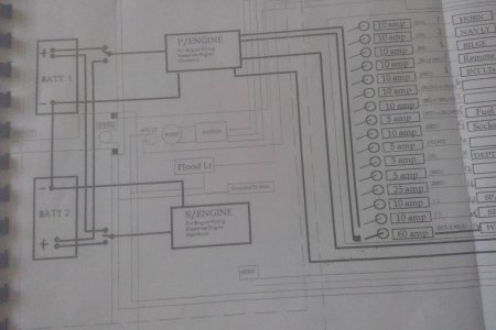
Here is a wiring Diagram

WIN_20240806_10_33_53_Pro.jpg
 

Tranona

Well-known member
Joined
10 Nov 2007
Messages
42,334
Visit site
Back last century, I sailed on a few boats doing RORC and JOG races, it was common to have a small sealed LA battery to operate the VHF. May even have been a rule for offshore? Some boats used that to avoid the GPS cutting out on engine start, because back then, it could take the GPS a long time to boot up again and find a fix, right when you actually want it.
That is all happening because the instruments are coming off the same battery as the starter, and yes, an independent power supply for the VHF is a coding requirement and commonly fitted to boats for racing. Not so relevant now that most boats have dedicated start batteries.
 

Tranona

Well-known member
Joined
10 Nov 2007
Messages
42,334
Visit site
Just to answer a few questions I do have seatalkNG, and as far as I know no extra wiring was put in for battery monitoring.
Here is a wiring Diagram

View attachment 181002
Your house circuits come off the port engine battery as suggested above several times. That is the explanation for the voltage drop in the MFD when starting that engine. Unlikely to indicate anything is wrong with the battery itself. To get an idea of battery state you need a monitor on the battery itself.

I would guess it has been like this for a very long time and provided you don't take too much out in the house side it works OK. However it would be better to have one battery dedicated to engine start and one to house with a means of connecting the house to the engine circuits in emergency. Your arrangement is common in smallish motor boats because house loads are relatively small compared with sailing boats and alternator running times greater to recharge batteries.
 

PaulRainbow

Well-known member
Joined
16 May 2016
Messages
17,050
Location
Suffolk
Visit site
If I have battery 1 on both, and battery 2 off will battery 1 start the starboard engine?
Each engine can be started from either or both batteries, but not if the switches are off.

Your system is basically what i described in post #11, with the added complication of 1-2-B switches. I't not a great system to be honest, I would swap the switches for standard on/off versions. The move some wiring so that battery 2 is for both engines and battery 1 is for the domestics. Add a 3rd on/off switch for emergencies.
 
Last edited:

pmagowan

Well-known member
Joined
7 Sep 2009
Messages
11,838
Location
Northern Ireland
sites.google.com
If wired as per diagram then no. The switch only connects the batteries rather than the engine so you still need to have the second switch engaged. Better wiring would give you the functionality above. You can set the switch for battery 2 in order to connect to bat 1

For clarity think of the switches as engine switches rather than battery. Engine corresponding to bat 1 (P engine) has a switch that will allow it to use 1/2 or both batteries. Engine at battery 2 (S engine) same. So you just need to deal with the switch closest to the engine in play
 
Last edited:

B27

Well-known member
Joined
26 Jul 2023
Messages
2,068
Visit site
I have never had my VSR allow voltage on the house bank to drop sufficiently to affect a plotter. When combined with the parallel switch the plotter would reboot on engine start with a setup I had on old boat but not with a VSR.
It can't happen with my VSR, because it only kicks in while the engine is running.
 

lustyd

Well-known member
Joined
27 Jul 2010
Messages
12,400
Visit site
The move some wiring so that battery 2 is for both engines and battery 1 is for the domestics. Add a 3rd on/off switch for emergencies
How would it charge the second battery? I don't see a VSR in there.

I do agree with the principal of the switches, much better arrangement.
 

Alex_Blackwood

Well-known member
Joined
19 May 2003
Messages
1,853
Location
Fareham
Visit site
Just to answer a few questions I do have seatalkNG, and as far as I know no extra wiring was put in for battery monitoring.
Here is a wiring Diagram

View attachment 181002
Been reading this thread and I am slightly confused. There is mention of 1-2-both switches. However the switches and arrangement in the diagram show two changeover switches which will allow either engine to be started from either battery or both engines from either battery but not either or both engines from both batteries in parallel 😵‍💫 :unsure: Am I correct or am I missing something obvious?:unsure:
 

Alex_Blackwood

Well-known member
Joined
19 May 2003
Messages
1,853
Location
Fareham
Visit site
I presumed the 1/2/B switches as it is schematically not shown, probably for simplicity.
Then it is wrong. Completely misleading, any electrical engineer or draughtsman would show the correct diagram. I needs clarifying IMO.
PS I would never presume with a circuit diagram.
 
Last edited:

wonkywinch

Well-known member
Joined
30 Jul 2018
Messages
2,029
Location
Hamble, UK
Visit site
And it shows loads only connected via the port engine. The schematic leaves a lot to be desired and can't be used for fault finding.
 

PaulRainbow

Well-known member
Joined
16 May 2016
Messages
17,050
Location
Suffolk
Visit site
I don't see anything wrong with the schematic.

It clearly shows all domestic loads being connected to the Port battery, which is a common system on small twin engine motor boats, which i described in post #11. Not that i like it.

As for the switch depictions, they clearly show 1-2-Off and the OP stated that they also have a Both setting, so i didn't find the depiction confusing. Not sure how you would depict them otherwise ? Perhaps add a label that says 1-2-Both ?
 

pmagowan

Well-known member
Joined
7 Sep 2009
Messages
11,838
Location
Northern Ireland
sites.google.com
Then it is wrong. Completely misleading, any electrical engineer or draughtsman would show the correct diagram. I needs clarifying IMO.
PS I would never presume with a circuit diagram.
Well the original circuit diagram is often not updated to include current setup. Since the OP talked about 1/2/B switches and the only switch in the diagram that would align with this is the one under discussion it is not such a big presumption. To be honest I would completely understand that the manufacturer might show a basic switch on the schematic but themselves have fitted a 1/2/B switch since the schematic appears very rudimentary. Not the best way to do things but don’t let perfection get in the way of life
 

Alex_Blackwood

Well-known member
Joined
19 May 2003
Messages
1,853
Location
Fareham
Visit site
I don't see anything wrong with the schematic.

It clearly shows all domestic loads being connected to the Port battery, which is a common system on small twin engine motor boats, which i described in post #11. Not that i like it.

As for the switch depictions, they clearly show 1-2-Off and the OP stated that they also have a Both setting, so i didn't find the depiction confusing. Not sure how you would depict them otherwise ? Perhaps add a label that says 1-2-Both ?
Paul, Surely you would show the connections and wiring for the "BOTH" arrangement.
I know I am probably being picky and understand what everyone says but was really just curious as to the apparent discrepancy between the diagram and OP's description. Not going to get my underwear knotted about it :ROFLMAO:
 
Top