An Affordable Lithium Boat Battery

migs

Active member
Joined
5 Jul 2011
Messages
129
Visit site
"That relay looks interesting. I cannot find any quiescent current on the datasheets so I assume its near zero."

Here's an explanation for non electronic geeks: a bistable (or latching) relay's contacts are held either open or closed by strong magnets. The contacts are flipped from one state to another by a short duration electromagnetic pulse provided by either one or two coils (I could explain about this further on request...). So, apart from the short (say 100ms) current pulse to change the relay's state, these relays consume no power at all.
 

migs

Active member
Joined
5 Jul 2011
Messages
129
Visit site
'At a 260A rating you are at the top end of many 35mm2 cable (cool/outside conduit) and some connectors (e.g. Anderson 170A) hence why they sensibly suggest 50mm2.

What size cables do you have?'


In a circuit, the cable size is determined by the fuse protecting the cable. All components in the circuit (such as a disconnect relay) must be rated higher than the fuse parameters, so it's not really the relay that determines cable size.

The process is: a) what does the load require, and is the power source sufficient b) chose cabling and distribution equipment to suit the load c) chose the protection equipment (e.g. fusing etc.) to suit the cabling and the load.

As it happens we are using 70mm2 cable with appropriate fusing to suit the cable and loads connected. It's good practice for the relay spec to be significantly higher than the minimum required...
 
Last edited:

noelex

Well-known member
Joined
2 Jul 2005
Messages
4,449
Visit site
"That relay looks interesting. I cannot find any quiescent current on the datasheets so I assume its near zero."

Here's an explanation for non electronic geeks: a bistable (or latching) relay's contacts are held either open or closed by strong magnets. The contacts are flipped from one state to another by a short duration electromagnetic pulse provided by either one or two coils (I could explain about this further on request...). So, apart from the short (say 100ms) current pulse to change the relay's state, these relays consume no power at all.
Good description.

The popular Blue sea ML Remote Battery Switch is really a latching relay and is popular in this application. They have a very high current limit and also can be manually switched. They are, however, expensive.

As they are a latching relay the only power consumed is while actually switching.

The alternative is a non latching relay/contactor, preferably with a built-in coil economiser. The coil econiser reduces the power consumption, although it is still higher than a true latching relay. They are sometimes easier to incorporate into the BMS than a latching relay. Some argue that this type of relay is safer than a latching relay, as they can be wired so that if all power is lost the relay will automatically open. A latching relay requires power to change states and this may not be present in some fault conditions.
 

migs

Active member
Joined
5 Jul 2011
Messages
129
Visit site
For a disconnect relay (or mosfet switch) failsafe is an interesting dilemma:

a) Fail-open and you lose all of your boats electrical equipment

b) Fail-closed and you could damage the battery by discharging it completely

Take your pick...
 

migs

Active member
Joined
5 Jul 2011
Messages
129
Visit site
'It took me 2 weeks to rewire my boat for lithium. We have numerous charging sources that were all configured for the lead batteries. Lots to change'

It took us 2 hours to rewire our boat for lithium. We have numerous charging sources that remained configured for lead batteries, but there was nothing to change. See article link in post #1 for details...
 

migs

Active member
Joined
5 Jul 2011
Messages
129
Visit site
For GHA:

It seems like setting a charger 'float' voltage of 13.35V is effectively using the charger in 'power supply mode'. Clearly this approach works in practice, but over a period of time, surely the total charge in and out won't balance and the batteries SOC will become unstable. I guess that as long as SOC remains within reasonable limits, that's ok. Do you have any information in this regard? Our system works completely differently, so I don't have a feel for how well the float method works.

Incidentally, how do Victron systems like yours know when to return to 'bulk' charging? Timer? Voltage? etc.
 

GHA

Well-known member
Joined
26 Jun 2013
Messages
12,257
Location
Hopefully somewhere warm
Visit site
For GHA:

It seems like setting a charger 'float' voltage of 13.35V is effectively using the charger in 'power supply mode'. Clearly this approach works in practice, but over a period of time, surely the total charge in and out won't balance and the batteries SOC will become unstable. I guess that as long as SOC remains within reasonable limits, that's ok. Do you have any information in this regard? Our system works completely differently, so I don't have a feel for how well the float method works.

Incidentally, how do Victron systems like yours know when to return to 'bulk' charging? Timer? Voltage? etc.
the SOC displayed by the victron goes out of sync slowly but doesn't really matter, the batteries get back up to the same SOC pretty much every day as bulk cuts off towards fully charged at the same distance up the knee when the voltage starts to rise quickly. The victon will lose mabye half a percent per day in error. Even with no Preukerts & 100% efficiency. Makes no difference other than numbers on a display. The regulators go back to bulk if the voltage drops whatever the figure is below float, doesn't happen very often, maybe using large loads on the inverter. Then same again, bulk cuts off at the same point up the knee. One day I'll decide a figure for fully charged and see what the SOC actually is at that point of the knee. Probably about 90, maybe 95%. Voltage is so stable doesnt really matter how much the solar is putting out, will only be a tiny bit off the same SOC.
 

migs

Active member
Joined
5 Jul 2011
Messages
129
Visit site
'the batteries get back up to the same SOC pretty much every day as bulk cuts off towards fully charged'

'The regulators go back to bulk if the voltage drops whatever the figure is below float, doesn't happen very often'


How does bulk cut in every day if it is triggered by the battery's voltage dipping below float. Surely, the voltage could dip every few seconds, or months according to load, so why every day?

Does bulk mode cut in at say 1mV below float voltage or is there some user setting?

I'm not particularly bothered about SOC monitor accuracy, just about the pattern of actual battery SOC variance over time i.e. hourly, daily, weekly etc. if permanenly on float.
 

geem

Well-known member
Joined
27 Apr 2006
Messages
7,443
Location
Caribbean
Visit site
'It took me 2 weeks to rewire my boat for lithium. We have numerous charging sources that were all configured for the lead batteries. Lots to change'

It took us 2 hours to rewire our boat for lithium. We have numerous charging sources that remained configured for lead batteries, but there was nothing to change. See article link in post #1 for details...
We have a complicated boat. Diesel genset. Duogen wind/water charging, a 3000w inverter charger, two more mains chargers, watermaker, now four battery banks, the boat was originally all electric when it was built in 1980. The original wiring is in excellent condition but the original Merlin Gerin breakers are obsolete and predate DIN rail. Lots of the work I did was a general electrical upgrade as well. New battery tie downs for all batteries, rewiring and relocating my Trojan bank, relocating existing desulphators, battery balancers, etc to make room for the new kit. Building a seperate battery box for the lithium.
The Trojan bank will go over the summer ready for the second lithium battery. This will give us 100% redundancy on the lithium system, in the event of a BMS fault that may switch off the existing lithium battery. Currently we can swap over to lead at the flick of a switch. Soon we will have minimised single point of failure.
 

GHA

Well-known member
Joined
26 Jun 2013
Messages
12,257
Location
Hopefully somewhere warm
Visit site
'the batteries get back up to the same SOC pretty much every day as bulk cuts off towards fully charged'

'The regulators go back to bulk if the voltage drops whatever the figure is below float, doesn't happen very often'


How does bulk cut in every day if it is triggered by the battery's voltage dipping below float. Surely, the voltage could dip every few seconds, or months according to load, so why every day?

Does bulk mode cut in at say 1mV below float voltage or is there some user setting?

I'm not particularly bothered about SOC monitor accuracy, just about the pattern of actual battery SOC variance over time i.e. hourly, daily, weekly etc. if permanenly on float.
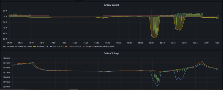
the solar regulators turn off at night, restart in bulk next day. smartsolar has a user setting, let me check...so mine are set so that if battery voltage goes down to 13.32v bulk will start again, 0.03v below float. Doesn't really need it, just ended up that way, sometimes restarts if the inverter is pulling a load of amps. Ah, good example just now, regs went to "float" at 14:40 then I just re-anchored to try and get out of the swell (it followed me 😂), windlass pulled the voltage down so regs went back to bulk for a few minutes, back to float at just before 16:001691334418799.png
 

noelex

Well-known member
Joined
2 Jul 2005
Messages
4,449
Visit site
How does bulk cut in every day if it is triggered by the battery's voltage dipping below float. Surely, the voltage could dip every few seconds, or months according to load, so why every day?
The return to bulk is controlled by the "bulk return voltage". This is sometimes called the "re-bulk voltage". Most units have a time delay on this of several seconds to avoid triggering this with short term low voltage spikes. So if the voltage drops below the bulk return voltage for longer than the programmed time delay, the charger will start a new bulk charging phase.

Some will also reset the absorption time causing a complete new bulk/absorption/float cycle, others, especially solar chargers, do not (this means once the voltage reaches the bulk voltage the charger will drop back to float skipping the absorption phase).

In addition to the above, most solar chargers will initiate a complete bulk/absorption/float cycle each solar day.

Victron does not use "bulk return voltage" but rather a "re-bulk voltage offset" The "bulk return voltage" = storage voltage - "re-bulk voltage offset". The net effect is the same.

On most chargers it is not possible for the user to adjust the bulk return voltage, it is typical set around 0.2v below the float setting. But on most Victron gear it is a user adjustable parameter. It is a setting that you should be careful adjusting from the default unless you have a good understanding of how the charge algorithm works.

Sorry for the long winded technical explanation, but you did ask :).
 
Last edited:

migs

Active member
Joined
5 Jul 2011
Messages
129
Visit site
By introducing a disconnect switch, lithium systems have actually taken a giant step backwards compared to lead as:

* Battery current delivery is throttled and the battery's source resistance increased

* A single point of failure has been added to the boat's primary circuit (no doubt relying on cheap and/or fake Chinese mosfets)

* An automatic control system with the authority to disconnect everything has been introduced (often with ill-designed and low quality software)

* The switch produces waste heat (i.e. efficiency losses and hot components), and switches with a reasonable current rating need fan cooling (i.e. fan failure and dust build up issues)

Systems like a REC BMS plus a Blue Sea contactor go someway to mitigate the above, but that solution is very expensive. Nevertheless, it's probably the only commercial system we would trust to keep the lights on.

100+ posts in and nobody has even mentioned our solution to the problem. (We expected howls of outrage and have been hiding behind the sofa in anticipation...)

PS. Please don't ask 'What is your solution?' as it's set out in the link on post #1
 

geem

Well-known member
Joined
27 Apr 2006
Messages
7,443
Location
Caribbean
Visit site
By introducing a disconnect switch, lithium systems have actually taken a giant step backwards compared to lead as:

* Battery current delivery is throttled and the battery's source resistance increased

* A single point of failure has been added to the boat's primary circuit (no doubt relying on cheap and/or fake Chinese mosfets)

* An automatic control system with the authority to disconnect everything has been introduced (often with ill-designed and low quality software)

* The switch produces waste heat (i.e. efficiency losses and hot components), and switches with a reasonable current rating need fan cooling (i.e. fan failure and dust build up issues)

Systems like a REC BMS plus a Blue Sea contactor go someway to mitigate the above, but that solution is very expensive. Nevertheless, it's probably the only commercial system we would trust to keep the lights on.

100+ posts in and nobody has even mentioned our solution to the problem. (We expected howls of outrage and have been hiding behind the sofa in anticipation...)

PS. Please don't ask 'What is your solution?' as it's set out in the link on post #1
You have a single point of failure with your system surely? A BMS, also a relay that can't be failed safe? You don't balance your cells but you explain that they are in balance but you don't know. You never get you cells onto the charge knuckle where evidence of well balanced cells would prevent itself.
You are now telling us we have a problem with our system that we don't recognise.
Our system uses mosfets like lots of other electronic equipment, autopilots, inverters, etc. The BMS temperature can be monitored. In 30degC air temperature and running a succession of high loads one after the other, I manage to get my BMS temperature to 43degC and the positive terminal of the battery to 34degC. We are talking of constant 2kw load. This was a test, to push the system beyond how we normally use it. It is not something that happens in real life. We are nowhere near stressing either battery or BMS.
We are only 100 days into lithium but we have done 27 cycles of a 24v, 280Ah DIY battery that has performed flawlessly. What am I missing?
We use a 200A BMS but dont need to go anywhere near that figure. That is its constant rating figure not it's maximum. Being a 24v boat does have some aevantage. Our maximum load is 1900w for 20 mins running the watermaker
 
  • Like
Reactions: vas

migs

Active member
Joined
5 Jul 2011
Messages
129
Visit site
Somebody hasn't read the article... we don't use a disconnect switch at all - for all the reasons above - plus the explanation in our submission.

'you explain that they [the cells] are in balance but you don't know'

Surely a system that always runs with a cell balance of <20mV and has a headroom of 800mV has balanced cells by definition. Again please refer to the article if you missed that point.

Yes indeed, howls of outrage; however, we still maintain that adding a cheap fet-based switch to your primary boat circuit is a step backwards compared to an old school direct connection. That was the essence of our previous post - nothing else...
 

migs

Active member
Joined
5 Jul 2011
Messages
129
Visit site
Here's our response (in advance) to the howls of anguish. Got to go sailing now - that's quite enough of enough of this armchair stuff for the moment...

*************************************************************************************************************************

Ah that's better; at last somebody has said 'you did what?!!!!' Our response: how did you feel about this extract from the article:

'On the other hand, if we fitted an automatic disconnect, safety-critical equipment such as nav lights, VHF etc. could stop working at exactly the wrong moment such as entering a harbour at night, or perhaps the bowthruster would shut down just when it was most needed. With an automatic disconnect power loss can occur at any time, and that seemed too great a risk.'

And most likely something about standards bodies will be needed at some point:

Standards can be very helpful; however, don't forget that RCD specified a five year life for seacocks that has left a legacy of dangerous brass fittings...
 

geem

Well-known member
Joined
27 Apr 2006
Messages
7,443
Location
Caribbean
Visit site
Here's our response (in advance) to the howls of anguish. Got to go sailing now - that's quite enough of enough of this armchair stuff for the moment...

*************************************************************************************************************************

Ah that's better; at last somebody has said 'you did what?!!!!' Our response: how did you feel about this extract from the article:

'On the other hand, if we fitted an automatic disconnect, safety-critical equipment such as nav lights, VHF etc. could stop working at exactly the wrong moment such as entering a harbour at night, or perhaps the bowthruster would shut down just when it was most needed. With an automatic disconnect power loss can occur at any time, and that seemed too great a risk.'

And most likely something about standards bodies will be needed at some point:

Standards can be very helpful; however, don't forget that RCD specified a five year life for seacocks that has left a legacy of dangerous brass fittings...
But if you install multiple batteries with their own BMS you have at least N+1 resilance. You don't have that
 

geem

Well-known member
Joined
27 Apr 2006
Messages
7,443
Location
Caribbean
Visit site
Somebody hasn't read the article... we don't use a disconnect switch at all - for all the reasons above - plus the explanation in our submission.

'you explain that they [the cells] are in balance but you don't know'

Surely a system that always runs with a cell balance of <20mV and has a headroom of 800mV has balanced cells by definition. Again please refer to the article if you missed that point.

Yes indeed, howls of outrage; however, we still maintain that adding a cheap fet-based switch to your primary boat circuit is a step backwards compared to an old school direct connection. That was the essence of our previous post - nothing else...
I think you are trying to sell your system to people they simply don't need it. It's great that you have built your own BMS. I am impressed, Like many thousands of people out there doing it, I am very happy with the system we have. BMS reliability has progressed substantially in a very short time. They are relatively cheap and it's easy to carry a spare. The active forums soon show up which BMS don't perform well. This is direct feedback from end users all over the world.
In the USA, drop in batteries are very popular and many thousands with FET based BMS are installed and working fine. I don't see any change in the market any time soon
 
  • Like
Reactions: vas

Kelpie

Well-known member
Joined
15 May 2005
Messages
7,767
Location
Afloat
Visit site
I was nervous about the 'lights going out' thing. Especially using a fairly cheap and basic BMS.
The solution? I kept my lead acid system and I run a handful of cabin lights off that, plus I have a simple changeover switch to allow me to run the navigation equipment from either lead or lithium. Takes about three seconds to do the switch.
In practice the only time we've had a BMS-induced shutdown was when safely anchored and cooking a steak dinner. Lost track of our current and the pepper sauce took us over the 120A limit. Which, sadly, killed the inverter. That's the only real problem we've had with the system to date and I think there was a good dose of bad luck involved.
 

geem

Well-known member
Joined
27 Apr 2006
Messages
7,443
Location
Caribbean
Visit site
I was nervous about the 'lights going out' thing. Especially using a fairly cheap and basic BMS.
The solution? I kept my lead acid system and I run a handful of cabin lights off that, plus I have a simple changeover switch to allow me to run the navigation equipment from either lead or lithium. Takes about three seconds to do the switch.
In practice the only time we've had a BMS-induced shutdown was when safely anchored and cooking a steak dinner. Lost track of our current and the pepper sauce took us over the 120A limit. Which, sadly, killed the inverter. That's the only real problem we've had with the system to date and I think there was a good dose of bad luck involved.
We also have a back up lead system, but that was when I was less confident about the reliability of my DIY lithium battery. Once we have the second lithium battery built and installed, the lead will go. I guess you are doing the same.
We have lots of headroom with our system, helped by being a 24v boat.
Inverter load is routinely less than 2000w on a 3000w inverter that will run 6000w peak. Its a high frequency inverter so reliable with inductive loads.
200A BMS with typical loads less than half it's constant rating. The second battery will reduce the BMS peak loading even more.
The 3000w inverter was selected for its ability to deal with inrush current on the 1.5kw watermaker motor.
We also love our Victron blue boxes🙂
 
Top